Special handling of 4D kinematics

|
Note!
The sequence of the rotations executed in succession can be selected via the Offset0-Subindex39 parameter. The following example describes the response in the standard setting 0: intrinsic x-y'-z" rotation. |
Permissible alignment of PCS, MCS and tools of 4D kinematics
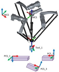
Possible parameterisation of different coordinate systems and tools of the Delta3_4dof axes group
Alignment of the robot (MCS)
The following applies to 4D kinematics: the Z axes of the WCS and MCS world and machine coordinate systems are aligned with each other and usually point "upwards". Rotations of the MCS around the x or y axis of the WCS cannot take place.
Alignment of the end effector to the robot
Furthermore the Z axis of the TCS end effector coordinate system is always directed so that it opposes the Z axis of the MCS (and therefore the WCS), which is synonymous to a gripper pointing "downwards".
Alignment of products (PCS)
The 16 product coordinate systems available can be positioned and aligned in any way irrespective of the kinematics, the following applying to 4D kinematics:
- The current position and orientation of the end effector ( MC_GroupReadActualPosition ) can be read out in the course of each PCS alignment process.
- Manual jog in the direction of the X PCS , Y PCS , and Z PCS axes can be carried out in the course of each PCS alignment process.
- Manual jog of orientations A and B (around the X PCS , Y PCS axes) is not possible, since these axes cannot be provided actively by the kinematics.
- Manual jog of orientation C (around the Z PCS axis) can only be carried out if the Z PCS axis is aligned with or directed so that opposes the Z WCS axis (i.e. PCS_1 and PCS_2, but not PCS_3 shown in the graphical representation above).
- Target positions for coordinated movements can only be specified in the PCS in which the Z PCS axis is aligned with or directed so that opposes the Z WCS axis (i.e. PCS_1 and PCS_2, but not PCS_3 in the above graphical representation).
- If the Cartesian C axis of the axes group is parameterised as Modulo axis, the end effector orientation in the PCS is represented in the value range 0°... 360° (for the alignment of PCS_1 or PCS_2).
- If the Cartesian C axis of the axes group is parameterised as Limited axis, the end effector orientation in the PCS is represented without any overflows (for the alignment of PCS_1 or PCS_2).
Example 1: The Z axes of WCS and PCS are alinged.
This example exclusively addresses the issue of orientation. The positions are not taken into consideration.
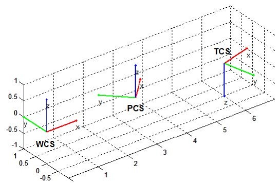
The PCS is parameterised as followed:
Orientation A := 0;
Orientation B := 0;
Orientation C := 45;
The orientation of the end effector (TCS) can be read out in the two coordinate systems via the MC_GroupReadActualPosition FB:
|
Read-out in the WCS coordinate system |
Read-out in the PCS coordinate system |
|---|---|
|
Position[4] := 180;
|
Position[4] := 180;
|
In this example (aligned Z axes), the "C" orientation of the "TCS" - represented in the "WCS" - is therefore identical to the difference of the single rotations:
C TCS in the WCS := C TCS in the PCS - C PCS in the WCS
After a full (negative) revolution of the C axis, this yields the following positions:
|
Read-out in the WCS coordinate system |
Read-out in the PCS coordinate system |
|---|---|
|
Position[4] := 180;
|
Position[4] := 180;
|
The sample positions specified apply to a C axis parameterised as "Limited". In the "Modulo" case, all position values are represented in the value range 0°... 360°.
Example 2: The Z axes of WCS and PCS are directed so that they oppose each other.
This example exclusively addresses the issue of orientation. The positions are not taken into consideration.
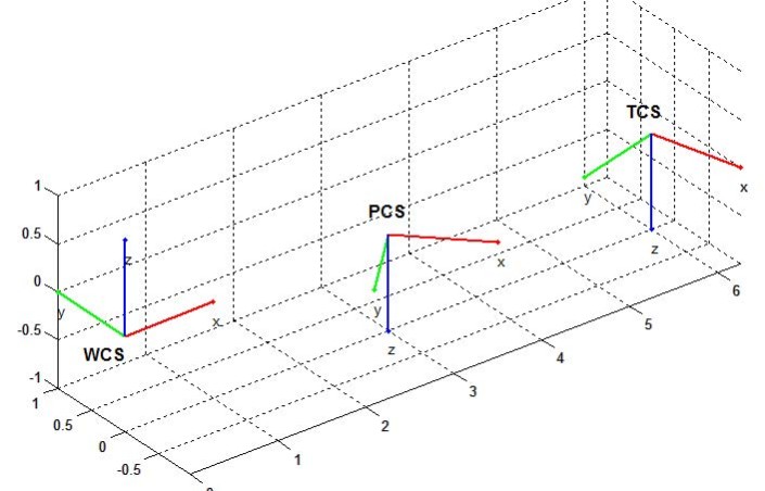
The PCS is parameterised as followed:
Orientation A := 180;
Orientation B := 0;
Orientation C := 45;
The orientation of the end effector (TCS) can be read out in the two coordinate systems via the MC_GroupReadActualPosition FB:
|
Read-out in the WCS coordinate system |
Read-out in the PCS coordinate system |
|---|---|
|
Position[4] := 180;
|
Position[4] := 0;
|
In this example (aligned Z axes), the "C" orientation of the "TCS" - represented in the "WCS" - is therefore identical to the sum of the single rotations:
C TCS in the WCS := C TCS in the PCS + C PCS in the WCS
After a full (positive) revolution of the C axis, this yields the following positions:
|
Read-out in the WCS coordinate system |
Read-out in the PCS coordinate system |
|---|---|
|
Position[4] := 180;
|
Position[4] := 0;
|
The sample positions specified apply to a C axis parameterised as "Limited". In the "Modulo" case, all position values are represented in the value range 0°... 360°.
Alignment of tools
Tools can only be shifted and rotated in the axes that can also be provided actively by the kinematics. For 4D axes groups this means that for tool transformations only displacements in X TCS , Y TCS , and Z TCS direction as well as rotations around the Z TCS axis (around the angle C) can be carried out.