Function assignment of the inputs and outputs (default setting)
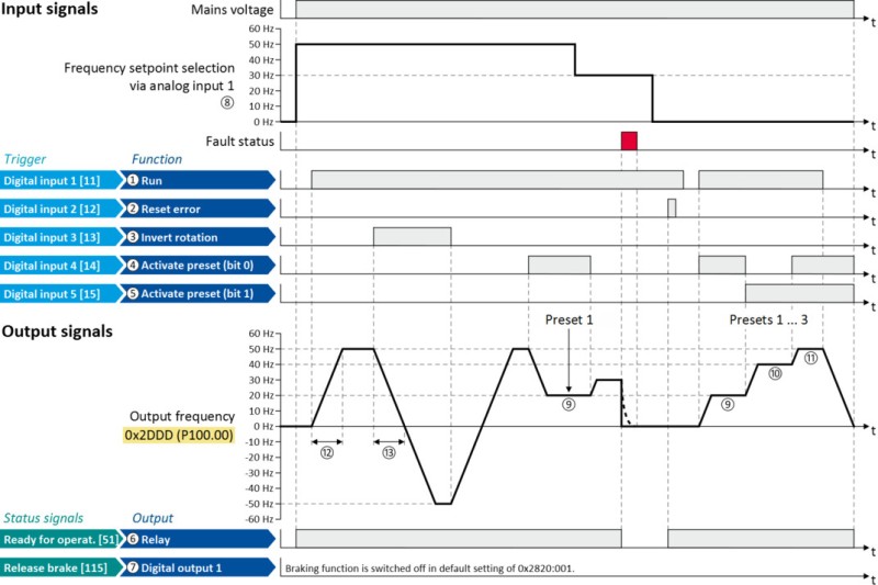
By default, the inverter can be controlled via the I/O terminals as follows:
|
Parameter
|
Designation
|
Default setting
|
||
|
Control functions
|
||||
|
①
|
0x2631:002
|
(P400.02)
|
Run
|
Digital input 1 [11]
|
|
②
|
0x2631:004
|
(P400.04)
|
Reset fault
|
Digital input 2 [12]
|
|
③
|
0x2631:013
|
(P400.13)
|
Reverse rotational direction
|
Digital input 3 [13]
|
|
④
|
0x2631:018
|
(P400.18)
|
Activate preset (bit 0)
|
Digital input 4 [14]
|
|
⑤
|
0x2631:019
|
(P400.19)
|
Activate preset (bit 1)
|
Digital input 5 [15]
|
|
Configuration of digital outputs
|
||||
|
⑥
|
0x2634:001
|
(P420.01)
|
Relay
|
Ready for operation [51]
|
|
⑦
|
0x2634:002
|
(P420.02)
|
Digital output 1
|
Release holding brake [115]
|
|
Settings for the frequency setpoint
|
||||
|
⑧
|
0x2860:001
|
(P201.01)
|
Frequency control: Default setpoint source
|
Analog input 1 [2]
|
|
⑨
|
0x2911:001
|
(P450.01)
|
Frequency setpoint presets: Preset 1
|
20 Hz
|
|
⑩
|
0x2911:002
|
(P450.02)
|
Frequency setpoint presets: Preset 2
|
40 Hz
|
|
⑪
|
0x2911:003
|
(P450.03)
|
Frequency setpoint presets: Preset 3
|
50 Hz
|
|
⑫
|
0x2917
|
(P220.00)
|
Acceleration time 1
|
5.0 s
|
|
⑬
|
0x2918
|
(P221.00)
|
Deceleration time 1
|
5.0 s
|
All functional possible settings for controlling the inverter are described in the "Start, stop and rotating direction commands" chapter.