Mechanical parameters
The mechanical parameters describe the motor end with reference to the mechanics used. The mechanical parameters are set in the »PLC Designer« on the Settings tab in the Mechanical parameters dialog level of the respective motion axis.
Total encoder resolution (subindex 28)
|
|
|||||||||||
|
This parameter serves to set the maximum display area of the encoder position to be read in. The maximum display area is calculated from the number of increments per revolution * representable revolutions. If the actual position is read in via an i700 or an encoder from the backplane bus, a representation of 32 bits must be parameterised. |
|||||||||||
|
Selection list (Lenze setting printed in bold) |
|
||||||||||
|
1024 |
10 bit Bit |
||||||||||
|
2048 |
11 bit Bit |
||||||||||
|
4096 |
12 bits Bit |
||||||||||
|
8192 |
13 bits Bit |
||||||||||
|
16384 |
14 bits Bit |
||||||||||
|
32768 |
15 bits Bit |
||||||||||
|
65536 |
16 bits Bit |
||||||||||
|
131072 |
17 bits Bit |
||||||||||
|
262144 |
18 bits Bit |
||||||||||
|
524288 |
19 bits Bit |
||||||||||
|
1048576 |
20 bits Bit |
||||||||||
|
2097152 |
21 bits Bit |
||||||||||
|
4194304 |
22 bits Bit |
||||||||||
|
8388608 |
23 bits Bit |
||||||||||
|
16777216 |
24 bits Bit |
||||||||||
|
33554432 |
25 bits Bit |
||||||||||
|
67108864 |
26 bits Bit |
||||||||||
|
134217728 |
27 bits Bit |
||||||||||
|
268435456 |
28 bits Bit |
||||||||||
|
536870912 |
29 bits Bit |
||||||||||
|
1073741824 |
30 bits Bit |
||||||||||
|
2147483648 |
31 bits Bit |
||||||||||
|
4294967295 |
32 bits Bit |
||||||||||
|
|
UNSIGNED_32 |
||||||||||


Virtual mode (subindex 29)
|
|
|||||||||||
|
This parameter serves to virtually switch a motion axis that is connected to a real drive. The axis then behaves like a virtual axis and the state of the connected real drive is ignored. This option can be used if the real axis is not available on the EtherCAT bus (EtherCAT node is deactivated in the device tree or configured as physically not available via the modular machine configuration) but is to be used in the project, e.g. as master axis or for testing the program execution. Note Function blocks that provide the functions for a real drive (e.g. L_MC1P_SetTorqueLimit or L_MC1P_GetDigInputsFromDrive) do not generate an error message when a real axis is used that is switched virtually. |
|||||||||||
|
Selection list (Lenze setting printed in bold) |
|
||||||||||
|
0 |
not active |
||||||||||
|
1 |
Active |
||||||||||
|
|
UNSIGNED_8 |
||||||||||

 Tip!
The current value of the Virtual mode parameter can be read out via the xVirtual output of the L_MC1P_ReadMachineData function block.
Traversing range
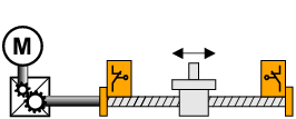
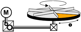
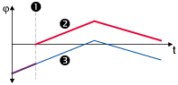
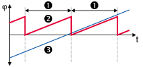
The selection of the traversing range in subindex 30 defines the machine measuring system.
Traversing range (subindex 30)
|
|
|||||||||||
|
Traversing range |
|||||||||||
|
Selection list (Lenze setting printed in bold) |
|
||||||||||
|
0 |
Modulo |
||||||||||
|
1 |
Limitation |
||||||||||
|
|
UNSIGNED_16 |
||||||||||
Tip!
The current value of the Traversing range parameter can be read out via the eTraversingRange output of the L_MC1P_ReadMachineData function block.
|
"Limited" traversing range |
"Modulo" traversing range |
|---|---|
|
|
|
Example: "Spindle drive" (linear axis) |
Example: "Turntable" |
|
|
|
Example: Position representation |
|
|
|


Cycle length (subindex 31)
|
|
|||||||||||
|
Cycle length |
|||||||||||
|
Setting range (min. value | unit | max. value) |
Lenze setting |
||||||||||
|
1e-009 |
Unit |
2147483647 |
360.0 unit |
||||||||
|
|
FLOAT_64 |
||||||||||
Tip!
The current value of the Cycle length parameter can be read out via the lrCycleLength output of the L_MC1P_ReadMachineData function block.
Feed constant
The feed constant to be set in subindex 32 corresponds to the movement of the machine during one revolution of the gearbox output shaft.
Feed constant (subindex 32)
|
|
|||||||||||
|
Feed constant |
|||||||||||
|
Setting range (min. value | unit | max. value) |
Lenze setting |
||||||||||
|
1e-009 |
Unit/rev |
2147483647 |
360.0 unit/rev |
||||||||
|
|
FLOAT_64 |
||||||||||
Tip!
The current value of the Feed constant parameter can be read out via the lrFeedConstant output of the L_MC1P_ReadMachineData function block.
In the case of a conveyor drive, the feed constant is obtained from the drive roll's circumference, which, in the following example, is calculated on the basis of the indicated diameter:
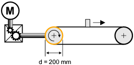

 [4-10] Schematic diagram: Feed constant for a conveyor driver
The feed constant of a spindle drive results from the leadscrew pitch. The feed constant specifies the path which the slide covers within one revolution of the spindle (in the following example 5.023 mm).
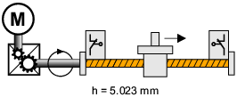
[4-11] Schematic diagram: Feed constant for a spindle drive
In the case of a rotary table and its specification as an angle, the feed constant is = 360°/revolution.
Gearbox ratio
The gearbox ratio indicates the number of revolutions of the motor axis it takes for exactly one revolution of the load axis (e.g. spindle or drive roll) to take place.
In the following example, one revolution of the spindle is carried out at exactly 58,667 revolutions of the motor axis:

[4-12] Schematic diagram of gearbox ratio
The data required for setting the gearbox ratio can be obtained from the technical data of the gearbox:
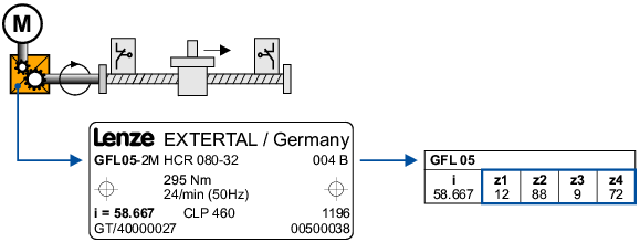
[4-13] Example: Technical data relating to the gearbox (from gearbox catalogue)
The gearbox ratio has to be set in the form of a quotient (numerator/denominator).
In order to specify the gearbox ratio exactly, use the number of teeth indicated on the data sheet or in the catalogue, if possible, instead of the information on the nameplate (see following calculation).




[4-14] Example calculation on the basis of the technical gearbox data
Resulting gear factor i is calculated as follows:
i= (gearbox factor numerator (subindex
33

Gearbox factor numerator (subindex 33)
|
|
|||||||||||
|
|
|||||||||||
|
Setting range (min. value | unit | max. value) |
Lenze setting |
||||||||||
|
1 |
|
4294967295 |
1 |
||||||||
|
|
UNSIGNED_32 |
||||||||||
Tip!
The current value of the Gearbox factor numerator parameter can be read out via the dwGearNumerator FB output of L_MC1P_ReadMachineData .
Gearbox factor denominator (subindex 34)
|
|
|||||||||||
|
Gearbox factor denominator |
|||||||||||
|
Setting range (min. value | unit | max. value) |
Lenze setting |
||||||||||
|
1 |
|
4294967295 |
1 |
||||||||
|
|
UNSIGNED_32 |
||||||||||
Tip!
The current value of the Gearbox factor denominator parameter can be read out via the dwGearDenominator FB output of L_MC1P_ReadMachineData .
Additional gearbox factor numerator (subindex 25)
|
|
|||||||||||
|
Additional gearbox factor numerator |
|||||||||||
|
Setting range (min. value | unit | max. value) |
Lenze setting |
||||||||||
|
1 |
|
4294967295 |
1 |
||||||||
|
|
UNSIGNED_32 |
||||||||||
Tip!
The current value of the Additional gearbox factor numerator parameter can be read out via the dwAddGearNumerator output of the L_MC1P_ReadMachineData function block.
Additional gearbox factor denominator (subindex 26)
|
|
|||||||||||
|
Additional gearbox factor denominator |
|||||||||||
|
Setting range (min. value | unit | max. value) |
Lenze setting |
||||||||||
|
1 |
|
4294967295 |
1 |
||||||||
|
|
UNSIGNED_32 |
||||||||||
Tip!
The current value of the Additional gearbox factor denominator parameter can be read out via the dwAddGearDenominator output of the L_MC1P_ReadMachineData function block.
Further mechanical parameters
Mounting direction (subindex 35)
|
|
|||||||||||
|
Motor installation direction
|
|||||||||||
|
Selection list (Lenze setting printed in bold) |
Info |
||||||||||
|
0 |
Cw |
Clockwise rotating motor = positive machine direction |
|||||||||
|
1 |
Ccw |
Counter-clockwise rotating motor = positive machine direction |
|||||||||
|
|
UNSIGNED_8 |
||||||||||
Tip!
The current value of the Mounting direction parameter can be read out via the xOrientation output of the L_MC1P_ReadMachineData function block.
Resolution of an encoder revolution (subindex 36)
|
|
|||||||||||
|
Resolution of an encoder revolution
|
|||||||||||
|
Setting range (min. value | unit | max. value) |
Lenze setting |
||||||||||
|
1 |
Inc / Rev |
4294967295 |
65536 Inc / Rev |
||||||||
|
|
UNSIGNED_32 |
||||||||||
Tip!
The current value of the Resolution of an encoder revolution parameter can be read out via the dwPosResolution output of the L_MC1P_ReadMachineData function block.
Moment of inertia load (for feedforward control) (subindex 37)
|
|
|||||||||||
|
Moment of inertia of the load (with reference to the gearbox output)
|
|||||||||||
|
Setting range (min. value | unit | max. value) |
Lenze setting |
||||||||||
|
0 |
kg cm² |
2147483647 |
0.0 kg cm² |
||||||||
|
|
FLOAT_64 |
||||||||||
Moment of inertia of motor (subindex 38)
|
|
|||||||||||
|
Moment of inertia of the motor read out of the axis
This is used for an automatic calculation of a feedforward control torque
|
|||||||||||
|
Display area (min. value | unit | max. value) |
Initialization |
||||||||||
|
|
kg cm² |
|
0.0 kg cm² |
||||||||
|
|
FLOAT_64 |
||||||||||

Reference torque (subindex 39)
|
|
|||||||||||
|
Reference torque read out of the axis |
|||||||||||
|
Display area (min. value | unit | max. value) |
Initialization |
||||||||||
|
|
Nm |
|
0.0 Nm |
||||||||
|
|
FLOAT_64 |
||||||||||