For NEC Article 430-compliant operation with motor overload protection, do not change default settings 0x2D4B:002 (P308.02) and 0x2D4B:003 (P308.03)!
(0x2D4B:002 (P308.02) = "On [0], 0x2D4B:003 (P308.03) = "error [3]"). With these settings, the calculated thermal motor load is stored internally when the inverter is switched off and reloaded when it is switched back on. If monitoring is deactivated with setting 0x2D4B:003 (P308.03) = "No response [0]" or "Warning [1]", the motor overload protection is deactivated. For NEC Article 430-compliant operation in this mode, external overload protection must be provided by the end user.
Motor overload monitoring (i²xt)
This function monitors the thermal overload of the motor, taking the motor currents recorded and
a mathematical model as a basis.
a mathematical model as a basis.
 DANGER!
Fire hazard by overheating of the motor.
Possible consequences: Death or severe injuries
▶
To achieve full motor protection, an additional temperature monitoring function with a separate evaluation must be installed.
▶
When operating motors that are equipped with PTC thermistors or thermal contacts, always activate the PTC input. When used alone (without i2T monitoring), PTC thermistors or thermal contacts do not fulfil NEC conformity requirements according to article 430.
Details
This function only serves to functionally protect the motor. It is not suitable for safety-relevant protection against energy-induced hazards, since the function is not fail-safe.
–
When the thermal motor utilisation calculated reaches the threshold set in 0x2D4B:001 (P308.01), the response set in 0x2D4B:003 (P308.03) is triggered.
–
With the setting 0x2D4B:003 (P308.03) = "No response [0]", the monitoring function is deactivated.

When monitoring the motor temperature with a suitable temperature sensor at terminals X109/T1 and X109/T2: if the motor temperature monitoring is set (0x2D4B:002 (P308.02) to "Error [3]"), the motor overload monitoring (0x2D4B:003 (P308.03)) can also be set differently to "Error [3]".
If the monitoring has the setting (0x2D4B:003 (P308.03) = "No reaction [0]" or "Warning [1]"), the motor overload protection is deactivated. For NEC Article 430-compliant operation in this mode, external overload protection must be provided by the end user.
If the monitoring has the setting (0x2D4B:003 (P308.03) = "No reaction [0]" or "Warning [1]"), the motor overload protection is deactivated. For NEC Article 430-compliant operation in this mode, external overload protection must be provided by the end user.
 Motor temperature monitoring
The following two diagrams show the relation between the motor load and tripping time of the monitoring under the following conditions:
–
Maximum utilization 0x2D4B:001 (P308.01) = 150 %
–
Speed compensation 0x2D4B:002 (P308.02) = "Off [1]" or output frequency ≥ 40 Hz
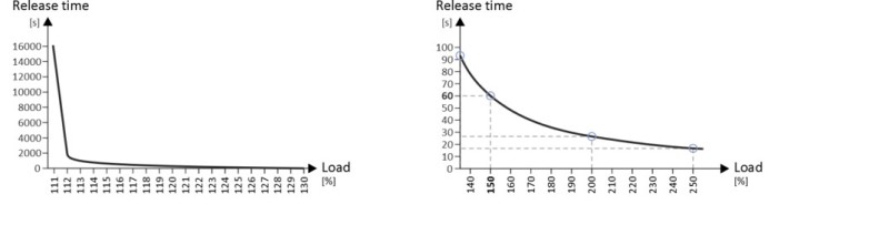
|
Maximum utilization 60s [%]
|
Load ratio [%]
|
Tripping time [s]
|
|
150
|
110
|
Indefinite
|
|
150
|
135
|
93
|
|
150
|
150
|
60
|
|
150
|
200
|
26
|
|
150
|
250
|
17
|
 0x2D4B:001 (P308.01)
|
Calculation
|
|
Load ratio:
|
|
Load ratio = actual motor current 0x2D88 (P104.00) / rated motor current 0x6075 (P323.00)
|
|
Maximum load ratio for continuous operation at an output frequency ≥ 40 Hz:
|
|
Maximum load ratio for continuous operation [%] = 0.73 * maximum utilization 0x2D4B:001 (P308.01)
|
|
Release time at an output frequency ≥ 40 Hz and a load ratio > maximum load ratio for continuous operation:
|
|
Tripping time [s] ≈ 15.9 / ((load ratio/maximum utilization 0x2D4B:001 (P308.01)) – 0.724) [s]
|
Speed compensation for protecting motors at low speed
The inverter has implemented a compensation for low speeds. If the motor is operated with frequencies below 40 Hz, the speed compensation in 0x2D4B:002 (P308.02) must be set to "On [0]" (default). This setting ensures that the tripping time for the monitoring is reduced at low speeds, in order to take the reduced self-cooling of AC motors into account.
For UL-compliant operation, speed compensation must also be activated. 0x2D4B:002 (P308.02) = "On [0]".
If speed compensation is activated, the maximum load ratio for continuous operation is reduced as follows:
|
Calculation
|
|
Output frequency < 40 Hz:
|
|
Maximum load ratio for continuous operation = 62.5 % + 37.5 % * output frequency [Hz] / 40 [Hz]
|
|
Output frequency ≥ 40 Hz:
|
|
No reduction
|
The following diagram shows the reduced release time with activated speed compensation.
–
Maximum utilization 0x2D4B:001 (P308.01) = 150 %
–
Speed compensation 0x2D4B:002 (P308.02) = "On [0]"
–
Load ratio = 150 %
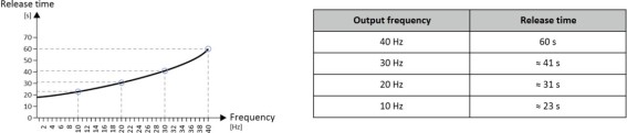
The following diagram shows the possible permanent load with activated speed compensation without the monitoring being triggered.
–
Maximum utilization 0x2D4B:001 (P308.01) = 150 %
–
Speed compensation 0x2D4B:002 (P308.02) = "On [0]"
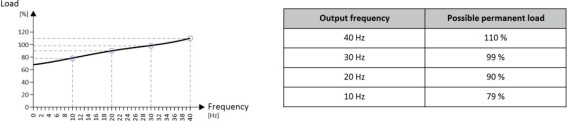
At of 0 Hz, only a load of max. 62.7 % (≈ 62.5 %) is possible. Reference: Load at 40 Hz (69 / 110 * 100 % = 62.7 %). The maximum possible motor load changes proportionally to the setting in 0x2D4B:001 (P308.01).
|
Calculation
|
|
Maximum load ratio for continuous operation at an output frequency < 40 Hz:
|
|
Maximum load ratio for continuous operation = kf = 0.625 + 0.375/40 * output frequency
|
|
Release time at maximum load ratio for continuous operation:
|
|
Release time at maximum load ratio for continuous operation [%] = 0.73 * kf * maximum utilization 0x2D4B:001 (P308.01)
|
|
Release time at an output frequency < 40 Hz and a load ratio > maximum load ratio for continuous operation:
|
|
Release time [s] ≈ 15.9 / ((load ratio/maximum utilization 0x2D4B:001 (P308.01) *kf)) – 0.724) [s]
|
Parameter
|
Address
|
Name / setting range / [default setting]
|
Information
|
|
|
0x2D4B:001
(P308.01)
|
Motor overload monitoring (i²xt): Maximum utilisation [60 s]
(Motor overload: Max.load.for 60s)
30 ... [150] ... 200 %
|
Maximum permissible thermal motor utilisation (max. permissible motor current for 60 seconds).
–
100 % = Rated motor current 0x6075 (P323.00)
–
If the motor is actuated with the current set here for 60 seconds, the maximum permissible thermal motor utilisation is reached and the response set in 0x2D4B:003 (P308.03) is executed.
–
If the motor is actuated with a different current, the time period until the motor overload monitoring function is activated is different. Generally the following applies: the lower the current, the lower the thermal utilisation and the later the monitoring function is triggered.
|
|
|
0x2D4B:002
(P308.02)
|
Motor overload monitoring (i²xt): Speed compensation
(Motor overload: Speed comp.)
|
Use this function to protect motors that are actuated at a speed below 40 Hz.
–
UL-compliant operation with motor overload protection requires the setting "On [0]"!
|
|
|
0
|
On
|
Release time for motor overload monitoring is reduced in order to compensate for the reduced cooling of naturally ventilated AC induction motors during operation at low speed.
|
|
|
1
|
Off
|
Function deactivated, no reduction of the motor overload monitoring release time. May require an external motor overload protection for the UL-compliant operation.
|
|
|
0x2D4B:003
(P308.03)
|
Motor overload monitoring (i²xt): Response
(Motor overload: Response)
|
Selection of the response to the triggering of motor overload monitoring.
–
UL-compliant operation with motor overload protection requires the setting "error [3]"!
–
If monitoring is deactivated by the setting 0x2D4B:003 (P308.03) = "No response [0]", no motor overload protection is active. In this case, an external motor overload protection can be provided by the user for a UL-compliant operation.
|
|
|
0
|
No response
|
||
|
1
|
Warning
|
||
|
2
|
Trouble
|
||
|
3
|
Fault
|
||
|
0x2D4B:005
|
Motor overload monitoring (i²xt): Thermal load
–
Read only
|
Display of the value of the internal i²*t integrator.
–
37500 = 100 % thermal load
–
When power is switched off, this value is saved in the internal EEPROM.
–
When power is switched on, the saved value is reloaded into the i²*t integrator.
–
The internal i²*t integrator detects the thermal load based on the load conditions even if the motor overload monitoring is deactivated.
|
|
|
0x2D4F
(P123.00)
|
Motor utilisation (i²xt)
(Mot. i2t utilis.)
–
Read only: x %
|
Display of the current thermal motor utilisation.
|
|