Configuring the process controller
By means of the process controller, a process variable can be regulated, for instance the pressure of a pump. The process controller is also referred to as "PID controller" (PID controller = proportional, integral and differential controller).
The process controller is part of a closed control loop. The variable to be influenced (controlled variable) is measured continuously by means of a sensor and supplied to the inverter as an analog signal (actual value) which, in the inverter, is then compared to the reference value (setpoint). The system deviation resulting therefrom is supplied to the process controller which, on this basis, decelerates or accelerates the motor speed according to the desired dynamic performance of the control loop, so that, for instance, a pump always generates the desired pressure.
Connection plan (example)
The following sample connection plan shows the control of a pump ①. The feedback of the variable (here: pressure) takes place via a pressure transducer ② connected to the analog input 1.
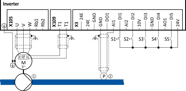
The digital inputs can be used to activate functions of the process controller. The specific assignment of the digital inputs and type of the contacts (switches or buttons, normally-closed contacts or normally-open contacts) depends on the application.
General information on the setting
–
First implement the basic setting of the frequency control. Basic setting
 –
The basic setting of the process controller is described in the following subchapter. Basic setting
Basic setting –
Optionally, the motor can be put into an energy-saving sleep mode if no power is required. Process controller sleep mode
Process controller sleep mode –
The rinsing function which can be activated in addition accelerates the motor in idle state to a defined speed at regular intervals.The rinsing of a pipe system with a pump that has been in an inactive state for a longer period is a typical application. Process controller rinse function
Process controller rinse function