ArticulatedP_4dof
The "ArticulatedP_4dof" axes group describes a spatial articulated robot with forcibly guided horizontal end effector orientation.
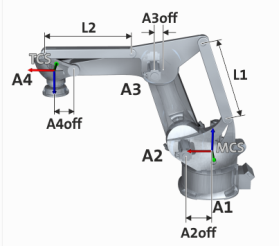
Degrees of freedom (dof)
|
Degrees of freedom (dof) |
Translation |
Rotation |
|---|---|---|
|
Drives |
- |
A1, A2, A3, A4 |
|
Tool |
x, y, z |
C |
MCS position
- Z axis is aligned with the first rotary axis.
- When angle setting A1 = 0 °, x axis points towards A2/towards the end effector.
- Y axis results from the Cartesian coordinate system.
- The origin of the coordinate system is on a level with the rotary axis A2.
TCS position
-
Z axis in direction of impact of the robot
 Aligned opposite to z
MCS
.
- In zero position, x TCS and x MCS are parallel.
- In zero position, the origin is z MCS = L1.
Zero position of the drives
- In the zero position of the drives, the first element is aligned in z MCS direction and the second element is aligned along the x MCS axis.
- The x axis of the TCS is parallel to X MCS .
- The Y and Z axes of TCS and MCS are antiparallel.
- The end effector (TCS) is on Z MCS = L1.
Parameter
A complete list of all kinematics-independent parameters can be found in the section
 Short overview of all parameters
|
Horizontal offset of axis 2 to axis 1 (A2 OFF )
|
|||||||||||
|
Setting range (min. value | unit | max. value) |
Lenze setting |
||||||||||
|
0 |
mm |
2147483647 |
0 mm |
||||||||
|
|
FLOAT_64 |
||||||||||


|
Length of arm 1 (L1)
|
|||||||||||
|
Setting range (min. value | unit | max. value) |
Lenze setting |
||||||||||
|
0 |
mm |
2147483647 |
0 mm |
||||||||
|
|
FLOAT_64 |
||||||||||
|
Horizontal offset of axis 3 to the passive joint of arm 1 at the parallelogram (A3 OFF )
|
|||||||||||
|
Setting range (min. value | unit | max. value) |
Lenze setting |
||||||||||
|
0 |
mm |
2147483647 |
0 mm |
||||||||
|
|
FLOAT_64 |
||||||||||
|
Length of arm 2 (L2)
|
|||||||||||
|
Setting range (min. value | unit | max. value) |
Lenze setting |
||||||||||
|
0 |
mm |
2147483647 |
0 mm |
||||||||
|
|
FLOAT_64 |
||||||||||
Axis offset A4Off (index offset 3, subindex 6)
|
Horizontal offset of axis 4 to the passive joint of arm 2 at the end effector (A4 OFF )
|
|||||||||||
|
Setting range (min. value | unit | max. value) |
Lenze setting |
||||||||||
|
0 |
mm |
2147483647 |
0 mm |
||||||||
|
|
FLOAT_64 |
||||||||||
Mounting location A3 (index offset 3, subindex 10)
|
This parameter serves to switch over between two typical versions of kinematics ArticulatedP_4dof. |
|||||||||||
|
Selection list (Lenze setting printed in bold) |
Info |
||||||||||
|
0 |
Elbow |
If the standard value Elbow is selected, the drive motor of elbow axis A3 is mounted in the elbow joint. The illustration above corresponds to this setting. |
|||||||||
|
1 |
Shoulder |
If the value Shoulder is selected, an alternative mechanical version is used for transformation. Here, the drive motor of elbow axis A3 on the robot basis is mounted coaxially to shoulder joint A2. The movement of the motor is transmitted to arm L2 through parallel motion. |
|||||||||
|
|
UNSIGNED_8 |
||||||||||