Coordinate systems
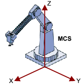
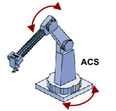
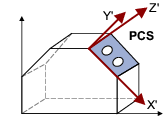
Coordinate systems are used to describe positions and orientations in the workspace as well as the current configuration of the machine. The directions of the coordinate systems are defined in the kinematics descriptions. A standard configuration (zero position) is described for each kinematic system.
|
Coordinate systems of kinematics |
||
|---|---|---|
|
Machine Coordinate System (MCS) |
Axis Coordinate System (ACS) |
Product Coordinate System (PCS_x) |
|
|
|
|

|
Please note!
If the reference coordinate system MCS has been shifted or rotated via parameters 121 ... 126 , the reference coordinate system WCS applies. |

 Tip!
The MCS , ACS and PCS coordinate systems are defined in the PLCopen specification " Function blocks for motion control, Part 4 - Coordinated Motion, Version 1.0 ".
World Coordinate System (WCS)
The WCS is a reference coordinate system that can be defined by the user. The possible definition of the WCS depends on the kinematics. By default, the WCS is congruent with the MCS when switched on.
Degrees of freedom of the WCS
- 2D kinematics (XZ) can be moved in the x and z directions and rotated around the y-axis (B-axis), as in all other cases a non-existent y-axis would have to be activated.
- 3D kinematics (XYZ) can be moved as required and rotated around all 3 axes, as they do not contain any rotation axes in the device tree.
- 4D kinematics (XYZC) can be moved in all directions. They can only be rotated around the z-axis, as otherwise the mechanical rotation would no longer coincide with the c-axis and inconsistencies would therefore occur in the device tree.
Machine Coordinate System (MCS)
The MCS is kinematics-dependent and cannot be shifted/orientated. The z-axis usually points "upwards" in the MCS.
The position of the MCS results from the design and, for some kinematics, also from the zero positions of the real drives. The 16 PCS are available for customised coordinate systems.
Axis Coordinate System (ACS)
The positive direction of rotation about coordinate axes is determined throughout according to the right-hand rule, i.e. the position of the z-axes in the sketches of the individual kinematic models determines the positive direction of movement of the output side.
The user must ensure that the zero position and the positive direction of rotation of the real drives match the defined zero position and direction of rotation of the respective kinematics.
Product Coordinate System (PCS_x)
PCS_1 ... PCS_16 are freely definable Cartesian or cylindrical coordinate systems. The MCS / PCS transformation can be set via the MC_SetCoordinateTransform and MC_SetCartesianTransform FBs.
By default, all PCS are congruent with the MCS when switching on.
|
|
Please note!
Note when using 4D kinematics:
See also: Special treatments for 4D kinematics |
Tool Coordinate System (TCS)
The TCS is kinematics-dependent and can be moved and orientated using tools. Programming a target position and orientation in one of the Cartesian coordinate systems ( WCS , MCS or PCS_x ) always describes the position of the TCS coordinates in the corresponding coordinate system.
The TCS can be moved and orientated by the user relative to the kinematics-specific starting position via a tool transformation.  Basics of tool management
Selection input CoordSystem / enumeration type L_MC4P_CoordSystem
The function blocks for coordinated multi-axis movements have a CoordSystem input that can be used to define the coordinate system to be used. The selection is made via the enumeration type L_MC4P_CoordSystem , for which the following constants (INT) are defined: