BeltKinematic_2dof
The "BeltKinematic_2dof" axle group describes two-dimensional belt kinematics as shown below:
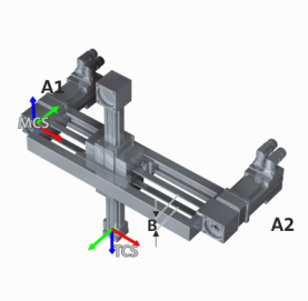
Degrees of freedom (dof)
Location of the MCS
- Identical direction of rotation (positive axis direction) of the drives defines the negative direction of the x-axis
- Opposite direction of rotation (positive direction of rotation A1, negative direction of rotation A2) defines the positive direction of the z-axis.
- The origin of the MCS is at the position of the end effector for A1 = 0 and A2 = 0.
Location of the TCS
- x TCS and x MCS are parallel.
- z TCS is orientated in the opposite direction to z MCS .
Zero setting of the drives
In the zero position, the origin of the TCS and the origin of the MCS are congruent.
Parameters
A complete list of all kinematics-independent parameters can be found in the section
 Brief overview of all parameters
|
Feed constant in units/revolution
|
|||||||||||
|
Setting range (min. value | unit | max. value) |
Lenze setting |
||||||||||
|
0 |
mm |
2147483647 |
0 mm |
||||||||
|
|
FLOAT_64 |
||||||||||


The feed constant corresponds to the effective circumference of the drive gears and can be roughly determined from the distance "B" between the horizontal belts:
|
|