LinearDelta3_4dof
The "LinearDelta3_4dof" axis group describes a three-dimensional parallel kinematic system with an additional axis of rotation C as shown below:
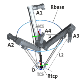
Degrees of freedom (dof)
Location of the MCS
- The origin lies in the centre of the circumcircle formed by the upper spherical joints of the parallelograms with the radius R BASE at axis position A1 = A2 = A3 = 0 mm.
- The xy plane of the MCS is horizontal, i.e. all drive axes are at an identical angle (linear angle a ) to the xy MCS plane.
- x-axis points in the direction of A1.
- z-axis points "upwards" away from the end effector.
Degrees of freedom of the MCS, relative to the WCS
The LinearDelta3_4dof axis group can be moved as required and rotated around the z-axis of the WCS.
Location of the TCS
- The origin lies in the centre of the circumcircle formed by the lower spherical joints of the parallelograms with the radius R TCP .
- x TCS and x MCS are parallel at A4 = 0°.
- z TCS is orientated in the opposite direction to z MCS .
Zero position of the axes
- In the zero position of the drives, the upper ball joints of the parallelogram struts lie in the x-y plane of the MCS.
- Axis A1, A2 and A3 must be at the same z-height with the same axis position.
- The axis A4 is exactly zero if the axes x TCS and x MCS are parallel, i.e. the axis x TCS points in the direction of A1.
- The positive direction of movement of the drives is downwards towards the apex of the triangular pyramid.
- The positive direction of rotation of A4 corresponds to a mathematical positive rotation around the z MCS axis.
Parameters
A complete list of all kinematics-independent parameters can be found in the section
 Brief overview of all parameters
|
Angle between base platform and drive axle |
|||||||||||
|
Setting range (min. value | unit | max. value) |
Lenze setting |
||||||||||
|
0 |
° |
90 |
0 ° |
||||||||
|
|
FLOAT_64 |
||||||||||


|
Length of the parallelogram
|
|||||||||||
|
Setting range (min. value | unit | max. value) |
Lenze setting |
||||||||||
|
0 |
mm |
2147483647 |
0 mm |
||||||||
|
|
FLOAT_64 |
||||||||||
|
Radius of the base platform (R BASE )
|
|||||||||||
|
Setting range (min. value | unit | max. value) |
Lenze setting |
||||||||||
|
0 |
mm |
2147483647 |
0 mm |
||||||||
|
|
FLOAT_64 |
||||||||||
|
Radius of the end effector (R TCP )
|
|||||||||||
|
Setting range (min. value | unit | max. value) |
Lenze setting |
||||||||||
|
0 |
mm |
2147483647 |
0 mm |
||||||||
|
|
FLOAT_64 |
||||||||||
|
Distance between the parallelogram struts (D)
|
|||||||||||
|
Setting range (min. value | unit | max. value) |
Lenze setting |
||||||||||
|
0 |
mm |
2147483647 |
0 mm |
||||||||
|
|
FLOAT_64 |
||||||||||