Delta3_4dof
The axis group "Delta3_4dof" describes three-dimensional parallel kinematics with an additional axis of rotation C as shown below:
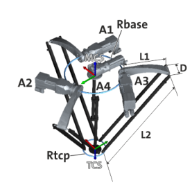
Degrees of freedom (dof)
Location of the MCS
- The origin lies in the centre of the circumcircle formed by A1, A2 and A3 with the radius R BASE .
- The drives are located in the x-y plane.
- x-axis points in the direction of A1.
- z-axis points "upwards" away from the end effector.
Degrees of freedom of the MCS, relative to the WCS
The axis group Delta3_4dof can be moved as required and rotated around the z-axis of the WCS.
Location of the TCS
- The origin lies in the centre of the circumference formed by the passive ball joints with the radius R TCP .
- x TCS and x MCS are parallel at A4 = 0°.
- z TCS is orientated in the opposite direction to z MCS .
Zero setting of the drives
- In the zero position of drives A1, A2 and A3, the toggle levers are "horizontal", i.e. the passive ball joints between the toggle lever and parallelograms are in the x-y plane of the MCS.
- Axis A4 is in the zero position precisely when the axes x TCS and x MCS are parallel to each other, i.e. the axis x TCS points in the direction of A1.
- A positive angle for A1 to A3 means that the knee lever moves "upwards".
- The positive direction of rotation of A4 corresponds to a mathematically positive rotation around the z MCS axis.
Parameters
A complete list of all kinematics-independent parameters can be found in the section
 Brief overview of all parameters
Arm length L1 (index offset 3, subindex 2)
|
Length of the knee lever (L1)
|
|||||||||||
|
Setting range (min. value | unit | max. value) |
Lenze setting |
||||||||||
|
0 |
mm |
2147483647 |
0 mm |
||||||||
|
|
FLOAT_64 |
||||||||||


Arm length L2 (index offset 3, subindex 3)
|
Length of the parallelogram (L2)
|
|||||||||||
|
Setting range (min. value | unit | max. value) |
Lenze setting |
||||||||||
|
0 |
mm |
2147483647 |
0 mm |
||||||||
|
|
FLOAT_64 |
||||||||||
Base radius Rbase (index offset 3, subindex 4)
|
Radius of the base platform (R BASE )
|
|||||||||||
|
Setting range (min. value | unit | max. value) |
Lenze setting |
||||||||||
|
0 |
mm |
2147483647 |
0 mm |
||||||||
|
|
FLOAT_64 |
||||||||||
End effector radius Rtcp (index offset 3, subindex 5)
|
Radius of the end effector (R TCP )
|
|||||||||||
|
Setting range (min. value | unit | max. value) |
Lenze setting |
||||||||||
|
0 |
mm |
2147483647 |
0 mm |
||||||||
|
|
FLOAT_64 |
||||||||||
Parallelogram width D (index offset 3, subindex 6)
|
Distance between the parallelogram struts (D)
|
|||||||||||
|
Setting range (min. value | unit | max. value) |
Lenze setting |
||||||||||
|
0 |
mm |
2147483647 |
0 mm |
||||||||
|
|
FLOAT_64 |
||||||||||
Coulomb friction A1 (index offset 3, sub-index 51)
|
Setting range (min. value | unit | max. value) |
Lenze setting |
||||||||||
|
0 |
Nm |
2147483647 |
0 Nm |
||||||||
|
|
FLOAT_64 |
||||||||||
Coulomb friction A2 (index offset 3, sub-index 52)
|
Setting range (min. value | unit | max. value) |
Lenze setting |
||||||||||
|
0 |
Nm |
2147483647 |
0 Nm |
||||||||
|
|
FLOAT_64 |
||||||||||
Coulomb friction A3 (index offset 3, sub-index 53)
|
Setting range (min. value | unit | max. value) |
Lenze setting |
||||||||||
|
0 |
Nm |
2147483647 |
0 Nm |
||||||||
|
|
FLOAT_64 |
||||||||||
Coulomb friction A4 (index offset 3, subindex 54)
|
Setting range (min. value | unit | max. value) |
Lenze setting |
||||||||||
|
0 |
Nm |
2147483647 |
0 Nm |
||||||||
|
|
FLOAT_64 |
||||||||||
Viscous friction A1 (index offset 3, sub-index 57)
|
Setting range (min. value | unit | max. value) |
Lenze setting |
||||||||||
|
0 |
Nm/(wheel/s) |
2147483647 |
0 Nm/(wheel/s) |
||||||||
|
|
FLOAT_64 |
||||||||||
Viscous friction A2 (index offset 3, sub-index 58)
|
Setting range (min. value | unit | max. value) |
Lenze setting |
||||||||||
|
0 |
Nm/(wheel/s) |
2147483647 |
0 Nm/(wheel/s) |
||||||||
|
|
FLOAT_64 |
||||||||||
Viscous friction A3 (index offset 3, sub-index 59)
|
Setting range (min. value | unit | max. value) |
Lenze setting |
||||||||||
|
0 |
Nm/(wheel/s) |
2147483647 |
0 Nm/(wheel/s) |
||||||||
|
|
FLOAT_64 |
||||||||||
Viscous friction A4 (index offset 3, sub-index 60)
|
Setting range (min. value | unit | max. value) |
Lenze setting |
||||||||||
|
0 |
Nm/(wheel/s) |
2147483647 |
0 Nm/(wheel/s) |
||||||||
|
|
FLOAT_64 |
||||||||||
Gravity x (index offset 3, subindex 71)
|
Setting range (min. value | unit | max. value) |
Lenze setting |
||||||||||
|
-10 |
m/s² |
10 |
0 m/s² |
||||||||
|
|
FLOAT_64 |
||||||||||
Gravity y (index offset 3, subindex 72)
|
Setting range (min. value | unit | max. value) |
Lenze setting |
||||||||||
|
-10 |
m/s² |
10 |
0 m/s² |
||||||||
|
|
FLOAT_64 |
||||||||||
Gravity z (index offset 3, subindex 73)
|
Setting range (min. value | unit | max. value) |
Lenze setting |
||||||||||
|
-10 |
m/s² |
10 |
-9.81 m/s² |
||||||||
|
|
FLOAT_64 |
||||||||||
Torque pilot control: Minimum parameter1 (index offset 3, subindex 74)
|
Setting range (min. value | unit | max. value) |
Lenze setting |
||||||||||
|
0 |
|
2147483647 |
0 |
||||||||
|
|
FLOAT_64 |
||||||||||
Torque pilot control: Minimum parameter2 (index offset 3, subindex 75)
|
Setting range (min. value | unit | max. value) |
Lenze setting |
||||||||||
|
0 |
|
2147483647 |
0 |
||||||||
|
|
FLOAT_64 |
||||||||||
Torque pilot control: Minimum parameter3 (index offset 3, subindex 76)
|
Setting range (min. value | unit | max. value) |
Lenze setting |
||||||||||
|
0 |
|
2147483647 |
0 |
||||||||
|
|
FLOAT_64 |
||||||||||
Torque pilot control: Minimum parameter4 (index offset 3, subindex 77)
|
Setting range (min. value | unit | max. value) |
Lenze setting |
||||||||||
|
0 |
|
2147483647 |
0 |
||||||||
|
|
FLOAT_64 |
||||||||||
Torque pilot control: Minimum parameter5 (index offset 3, subindex 78)
|
Setting range (min. value | unit | max. value) |
Lenze setting |
||||||||||
|
0 |
|
2147483647 |
0 |
||||||||
|
|
FLOAT_64 |
||||||||||
Torque pilot control: Minimum parameter6 (index offset 3, subindex 79)
|
Setting range (min. value | unit | max. value) |
Lenze setting |
||||||||||
|
0 |
|
2147483647 |
0 |
||||||||
|
|
FLOAT_64 |
||||||||||
Torque pilot control: Minimum parameter7 (index offset 3, subindex 80)
|
Setting range (min. value | unit | max. value) |
Lenze setting |
||||||||||
|
0 |
|
2147483647 |
0 |
||||||||
|
|
FLOAT_64 |
||||||||||
A minimum parameter of the dynamics describes a mathematical summary of several physical masses, mass inertias and geometric lengths that lead to a robustly identifiable parameter set and a computationally efficient calculation rule for feedforward control.
|
MinimalDynamicParameter 2 : = lrMassLever * (lrCenterOfMassLever - lrL1) |
|
|
MinimalDynamicParameter 3 : = lrMassRhomboid |
The minimum parameter 3 is identical to the mass of the parallelogram |
|
MinimalDynamicParameter 4 : = lrMassTCP |
The minimum parameter 4 is identical to the end effector mass |
|
MinimalDynamicParameter 5 : = 1/3 * lrMassCAxis1 * lrLengthCAxis1 2 + 1/12 * lrMassCAxis2 * lrLengthCAxis2 2 |
|
|
MinimalDynamicParameter 6 : = |
|
|
MinimalDynamicParameter 7 : = lrInertiaCAxis |
|
Related topics
Travel ranges of connected axes
Consideration of differential gears