Analog output 1

Settings for analog output 1.
 
Details
The analog output 1 is controlled with the signal selected in 0x2639:002 (P440.02).
The following settings are possible for the analog output:
–
Definition of the signal range ①
 
–
Definition of the output range ②

 
Diagnostic parameters:
–
The current output voltage is displayed in 0x2DAA:001 (P112.01).
 
–
The actual output current is displayed in 0x2DAA:002 (P112.02).
 
 
Definition of the signal range
The signal range results from the resolution of the selected signal multiplied by the set min and max signal value. Signals outside the signal range are cut off. For examples, see the following table:
Signal
Resolution
Min. signal
Max. signal
Signal range
Output frequency
0.1 Hz
0
1000
0 ... 100.0 Hz
Frequency setpoint
0.1 Hz
0
1000
0 ... 100.0 Hz
Analog input 1
0.1 %
0
1000
0 ... 100.0 %
Analog input 2
0.1 %
0
1000
0 ... 100.0 %
Motor current
0.1 A
0
100
0 ... 10.0 A
Output power
0.001 kW
0
250
0 ... 0.250 kW
Actual torque
0.1 % *
0
1000
0 ... 100.0 % *
NetWordIN3
0.1 %
200
500
20.0 ... 50.0 %
NetWordIN4
0.1 %
0
250
0 ... 25.0 %
* 100 % = Rated motor torque 0x6076 (P325.00)
 
Definition of the output range
The analog output can be configured as voltage source or current source. The output range selected in 0x2639:001 (P440.01) then corresponds to the configured signal range.
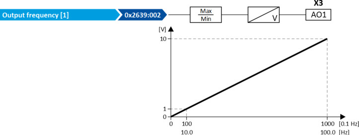
 
Configuration examples
Detailed configuration examples can be found in the following subchapters:
 
Parameter
Address
Name / setting range / [default setting]
Information
0x2639:001
(P440.01)
Analog output 1: Output range
(Analog output 1: AO1 outp. range)
Definition of the output range.
0
Inhibited
1
0 ... 10 VDC
2
0 ... 5 VDC
3
2 ... 10 VDC
4
4 ... 20 mA
5
0 ... 20 mA
11
0 ... 10 VDC (mirrored)
In these configurations, negative analog output values are symmetrically mirrored on the Y axis.
12
0 ... 5 VDC (mirrored)
13
2 ... 10 VDC (mirrored)
14
4 ... 20 mA (mirrored)
15
0 ... 20 mA (mirrored)
0x2639:002
(P440.02)
Analog output 1: Function
(Analog output 1: AO1 function)
Selection of the signal to be shown at analog output 1.
0
Not active
No output signal.
1
Output frequency
Actual output frequency (resolution: 0.1 Hz).
2
Frequency setpoint
Current frequency setpoint (resolution: 0.1 Hz).
3
Analog input 1
Input signal of analog input 1 (resolution: 0.1 %).
4
Analog input 2
Input signal of analog input 2 (resolution: 0.1 %).
5
Motor current
Actual motor current (resolution: 0.1 A).
6
Output power
Actual output power (resolution: 0.001 kW).
7
Torque actual value  
Current torque (resolution: 0.1 %).
–
100 % = permissible maximum torque 0x6072 (P326.00)
 
8
Actual motor frequency
Actual motor output frequency (resolution: 0.1 Hz).
10
Sequencer controlled  
Voltage value which has been set for the currently executed sequencer segment (resolution: 0.01 V).
11
DC-bus voltage
Current DC-bus voltage (resolution: 1 V).
12
Device utilisation (ixt)
Current device utilization (resolution: 1 %).
20
NetWordIN3
Actual value of the NetWordIN3 data word (resolution: 0.1 %).
21
NetWordIN4
Actual value of the NetWordIN4 data word (resolution: 0.1 %).
201
Internal value  
Internal values of the manufacturer.
202
Internal value  
203
Internal value  
204
Internal value  
205
Internal value  
206
Internal value  
0x2639:003
(P440.03)
Analog output 1: Min. signal
(Analog output 1: AO1 min. signal)
-2147483648 ... [0] ... 2147483647
Definition of the signal value that corresponds to the minimum value at analog output 1.
Example: configuration of analog output 1 as a 4 ... 20 mA current loop: output current 4 mA = 0x2639:003
0x2639:004
(P440.04)
Analog output 1: Max. signal
(Analog output 1: AO1 max. signal)
-2147483648 ... [1000] ... 2147483647
Definition of the signal value that corresponds to the maximum value at analog output 1.
Example: configuration of analog output 1 as a 4 ... 20 mA current loop: output current 20 mA = 0x2639:004
0x2639:006
(P440.06)
Analog output 1: Filter time
(Analog output 1: AO1 filter time)
0 ... [250] ... 10000 ms