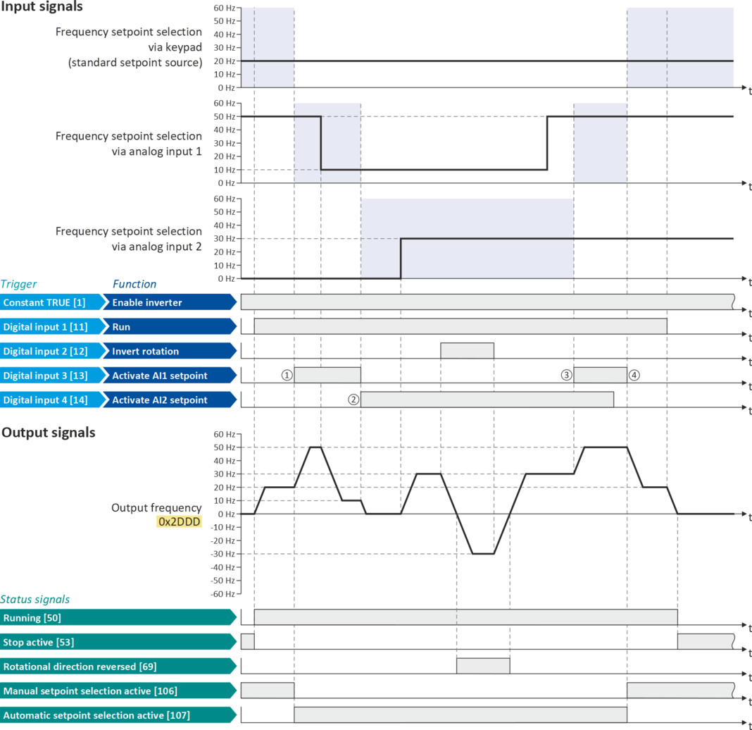
If S3 and S4 are actuated at the same time, the analog input 1 is active as setpoint source since the digital input 3 assigned to this function has a higher priority than the digital input 4.
Example: Change-over from keypad setpoint to AI1/AI2 setpoint
–
The keypad is set as standard setpoint source.
–
Switch S1 starts the motor in the forward direction of rotation. Switch S1 in initial position stops the motor again.
–
The switch S2 switches the direction of rotation.
–
The switch S3 activates analog input 1 as setpoint source.
–
The switch S4 activates analog input 2 as setpoint source.

|
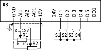
Connection diagram
|
Function
|
|
|
|
Potentiometer R1
|
Frequency setpoint selection via AI1
|
|
Potentiometer R2
|
Frequency setpoint selection via AI2
|
|
|
Switch S1
|
Run
|
|
|
Switch S2
|
Reverse rotational direction
|
|
|
Switch S3
|
Activate AI1 setpoint
|
|
|
Switch S4
|
Activate AI2 setpoint
|
|
|
Parameter
|
Name
|
Setting for this example
|
|
Enable inverter
|
Constant TRUE [1]
|
|
|
Run
|
Digital input 1 [11]
|
|
|
Reset fault
|
Not connected [0]
|
|
|
Reverse rotational direction
|
Digital input 2 [12]
|
|
|
Activate AI1 setpoint
|
Digital input 3 [13]
|
|
|
Activate AI2 setpoint
|
Digital input 4 [14]
|
|
|
Activate preset (bit 0)
|
Not connected [0]
|
|
|
Control selection
|
Flexible I/O configuration [0]
|
|
|
Stop method
|
Standard ramp [1]
|
|
|
Frequency control: Default setpoint source
|
Keypad [1]
|
|
The status signals can be assigned to digital outputs.
 Configure digital outputs |
|
|
|
|
|
①
|
The changeover is initiated from keypad setpoint (standard setpoint source) to AI1 setpoint.
|
|
②
|
The changeover is initiated from AI1 setpoint to AI2 setpoint.
|
|
③
|
The changeover is initiated from AI2 setpoint to AI1 setpoint since the digital input 3 has a higher priority than the digital input 4.
|
|
④
|
The changeover is initiated to keypad setpoint (standard setpoint source).
|