Manual release of the holding brake
The "Open holding brake" function serves to release the holding brake immediately. Brake application time and brake opening time as well as the conditions for the automatic operation are not effective.
Preconditions
–
Observe setting and application notes in the "Holding brake control" chapter!
–
The brake mode "Automatic [0]" or "Manual [1]" must be set in 0x2820:001 (P712.01).
–
The trigger "Release holding brake [115]" must be assigned to a digital output or, in the simplest
case, to the relay which then switches the brake supply.
Details
A manual opening of the holding brake is possible in the modes "Automatic [0]" and "Manual [1]" via the following external triggers:
–
Via bit 14 in the CiA control word 0x6040.
–
Via the trigger in 0x2631:049 (P400.49) assigned to the "Open holding brake" function.  Example for operating mode
 Parameter
|
Address
|
Name / setting range / [default setting]
|
Information
|
|
|
0x2631:049
(P400.49)
|
Function list: Open holding brake
(Function list: Open brake)
–
Setting can only be changed if the inverter is disabled.
–
Further possible settings:
 Trigger list |
Assignment of a trigger for the "Open holding brake" function.
Trigger = TRUE: open holding brake (immediately).
Trigger = FALSE: no action.
Notes:
–
Function is only executed if the brake mode 0x2820:001 (P712.01) is set to "Automatic [0]" or "Manual [1]".
CAUTION!
–
The manually triggered "Open holding brake" command has a direct impact on the "Release holding brake [115]" trigger. Thus, the holding brake can be manually released if the power section is switched off!
–
The responsibility for a manual opening of the holding brake lies with the external trigger source for the "Open holding brake" command!
|
|
|
0
|
Not connected
|
No trigger assigned (trigger is constantly FALSE).
|
|
 CAUTION!
Example for operating mode
–
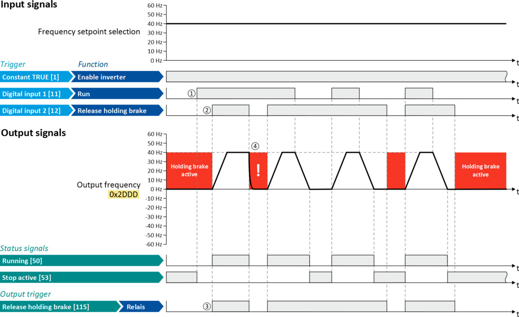
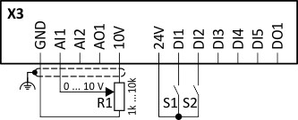
Switch S1 starts the motor in forward direction of rotation. Switch S1 in initial position stops the motor again.
–
Switch S2 opens the holding brake. For this purpose, in this example, trigger "Release holding brake [115]" is assigned to the relay that switches the brake supply.
|
Connection diagram
|
Function
|
|
|
|
Potentiometer R1
|
Frequency setpoint selection
|
|
Switch S1
|
Run
|
|
|
Switch S2
|
Open holding brake
|
|
|
Parameter
|
Name
|
Setting for this example
|
|
Enable inverter
|
Constant TRUE [1]
|
|
|
Run
|
Digital input 1 [11]
|
|
|
Reset fault
|
Not connected [0]
|
|
|
Open holding brake
|
Digital input 2 [12]
|
|
|
Relay
|
Release holding brake [115]
|
|
|
Control selection
|
Flexible I/O configuration [0]
|
|
|
Stop method
|
Standard ramp [1]
|
|
|
Frequency control: Default setpoint source
|
Analog input 1 [2]
|
|
The status signals can be assigned to digital outputs.
Configure digital outputs |
|
|
|
|
|
①
|
As the holding brake is active, the motor does not yet start to rotate after the start command.
|
|
②
|
The holding brake is opened. The motor is led to the setpoint.
|
|
③
|
In this example, the "Release holding brake [115]" trigger is assigned to the relay that switches the brake supply. In the sleep mode, the holding brake is applied. If the relay is energized, the holding brake is opened.
|
|
④
|
Note: Holding brakes are not intended for braking during operation.
The increased wear caused by braking during operation may destroy the holding brakes prematurely! |