Relay output
Settings for the relay.

Relay only switches if the inverter is supplied with 240 V or 400 V.
Use a corresponding suppressor circuit in case of an inductive or capacitive load!
Details
The relay is controlled with the trigger selected in 0x2634:001 (P420.01).
The following settings are possible for the relay:
–
Inversion ①
–
Switch-on delay ②
–
Cutout delay ③
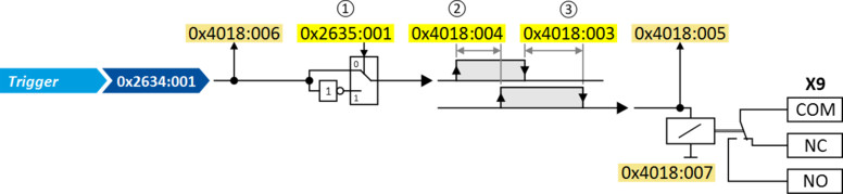
Diagnostic parameters:
–
The logic status of the trigger signal is displayed in 0x4018:006.
–
The logic status of the relay is displayed in 0x4018:005.
–
The current switching cycles of the relay are shown in 0x4018:007.
Parameter
|
Address
|
Name / setting range / [default setting]
|
Information
|
|
|
0x2634:001
(P420.01)
|
Digital outputs function: Relay
(Dig.out.function: Relay function)
|
Assignment of a trigger to the relay.
Trigger = FALSE: X9/NO-COM open and NC-COM closed.
Trigger = TRUE: X9/NO-COM closed and NC-COM open.
|
|
|
0
|
Not connected
|
No trigger assigned (trigger is constantly FALSE).
|
|
|
1
|
Constant TRUE
|
Trigger is constantly TRUE.
|
|
|
11
|
Digital input 1
|
State of X3/DI1, taking an inversion set in 0x2632:001 (P411.01) into consideration.
|
|
|
12
|
Digital input 2
|
State of X3/DI2, taking an inversion set in 0x2632:002 (P411.02) into consideration.
|
|
|
13
|
Digital input 3
|
State of X3/DI3, taking an inversion set in 0x2632:003 (P411.03) into consideration.
|
|
|
14
|
Digital input 4
|
State of X3/DI4, taking an inversion set in 0x2632:004 (P411.04) into consideration.
|
|
|
15
|
Digital input 5
|
State of X3/DI5, taking an inversion set in 0x2632:005 (P411.05) into consideration.
|
|
|
16
|
Digital input 6
|
State of X3/DI6, taking an inversion set in 0x2632:006 (P411.06) into consideration.
Digital input 6 is only available in the Control Unit (CU) with application I/O.
|
|
|
17
|
Digital input 7
|
State of X3/DI7, taking an inversion set in 0x2632:007 (P411.07) into consideration.
Digital input 7 is only available in the Control Unit (CU) with application I/O.
|
|
|
30
|
NetWordIN1 - bit 12
|
State of NetWordIN1/bit 12 ... 15.
–
Display of NetWordIN1 in 0x4008:001 (P590.01).
–
For implementing an individual control word format, NetWordIN1 can be mapped to a process data input word.
|
|
|
31
|
NetWordIN1 - bit 13
|
||
|
32
|
NetWordIN1 - bit 14
|
||
|
33
|
NetWordIN1 - bit 15
|
||
|
34
|
NetWordIN2 - bit 0
|
State of NetWordIN2/bit 0 ... bit 15.
–
Display of NetWordIN2 in 0x4008:002 (P590.02).
–
For controlling the digital outputs via network, NetWordIN2 can be mapped to a process data input word.
|
|
|
35
|
NetWordIN2 - bit 1
|
||
|
36
|
NetWordIN2 - bit 2
|
||
|
37
|
NetWordIN2 - bit 3
|
||
|
38
|
NetWordIN2 - bit 4
|
||
|
39
|
NetWordIN2 - bit 5
|
||
|
40
|
NetWordIN2 - bit 6
|
||
|
41
|
NetWordIN2 - bit 7
|
||
|
42
|
NetWordIN2 - bit 8
|
||
|
43
|
NetWordIN2 - bit 9
|
||
|
44
|
NetWordIN2 - bit 10
|
||
|
45
|
NetWordIN2 - bit 11
|
||
|
46
|
NetWordIN2 - bit 12
|
||
|
47
|
NetWordIN2 - bit 13
|
||
|
48
|
NetWordIN2 - bit 14
|
||
|
49
|
NetWordIN2 - bit 15
|
||
|
50
|
Running
|
TRUE if inverter and start are enabled and output frequency > 0 Hz. Otherwise FALSE.
Exception, quick stop mode: TRUE if inverter and start are enabled and output frequency > 0.2 Hz. Otherwise FALSE.
|
|
|
51
|
Ready for operation
|
TRUE if inverter is ready for operation (no error active, no STO active and DC-bus voltage ok). Otherwise FALSE.
|
|
|
52
|
Operation enabled
|
TRUE if inverter and start are enabled. Otherwise FALSE.
|
|
|
53
|
Stop active
|
TRUE if inverter is enabled and motor is not started and output frequency = 0.
|
|
|
54
|
Quick stop active
|
TRUE if quick stop is active. Otherwise FALSE.
|
|
|
55
|
Inverter disabled (safety)
|
TRUE if the integrated safety system has inhibited the inverter. Otherwise FALSE.
|
|
|
56
|
Fault active
|
TRUE if error is active. Otherwise FALSE.
|
|
|
57
|
Error (non-resettable) active
|
TRUE if non-resettable error is active. Otherwise FALSE.
|
|
|
58
|
Device warning active
|
TRUE if warning is active. Otherwise FALSE.
–
A warning has no impact on the operating status of the inverter.
–
A warning is reset automatically if the cause has been eliminated.
|
|
|
59
|
Device trouble active
|
TRUE if a fault is active. Otherwise FALSE.
–
In the event of a fault, the motor is brought to a standstill with the quick stop ramp. The inverter is then disabled.
–
Exception: In case of a serious fault, the inverter is disabled immediately. The motor has no torque (coasts).
–
The error state will be left automatically if the error condition is not active anymore.
–
The restart behaviour after trouble can be configured.
 Automatic restart after a fault |
|
|
60
|
Heatsink temperature warning active
|
TRUE if current heatsink temperature > warning threshold for temperature monitoring. Otherwise FALSE.
–
Display of the current heatsink temperature in 0x2D84:001 (P117.01).
–
Setting of the warning threshold in 0x2D84:002.
|
|
|
65
|
Motor PTC error active
|
TRUE if an error of the motor PTC has been detected. Otherwise FALSE.
–
The trigger is set irrespective of the response set in 0x2D49:002 (P309.02) when the motor temperature monitoring is triggered.
|
|
|
66
|
Flying restart circuit active
|
TRUE if flying restart circuit active is active. Otherwise FALSE.
|
|
|
67
|
DC braking active
|
TRUE if DC braking is active. Otherwise FALSE.
|
|
|
68
|
Stop command active
|
TRUE if delay to standstill active. Otherwise FALSE.
|
|
|
69
|
Rotational direction reversed
|
TRUE if output frequency is negative. Otherwise FALSE.
|
|
|
70
|
Frequency threshold exceeded
|
TRUE if current output frequency > frequency threshold. Otherwise FALSE.
–
Display of the current output frequency in 0x2DDD (P100.00).
–
Setting Frequency threshold in 0x4005 (P412.00).
|
|
|
71
|
Actual speed = 0
|
TRUE if actual output frequency = 0 Hz (
± 0.3 Hz), irrespective of the operating mode. Otherwise FALSE. |
|
|
72
|
Setpoint speed reached
|
TRUE if frequency setpoint reached. Otherwise FALSE.
|
|
|
73
|
PID feedback = setpoint
|
TRUE if the controlled feedback variable = process controller setpoint (± in 0x404D:003 (P608.03) set hysteresis). Otherwise FALSE.
|
|
|
74
|
PID sleep mode active
|
TRUE if the inverter is in "PID sleep mode". Otherwise FALSE.
|
|
|
75
|
PID MIN alarm active
|
TRUE if feedback variable (with activated PID control) < MIN alarm threshold. Otherwise FALSE.
|
|
|
76
|
PID MAX alarm active
|
TRUE if the feedback variable (with activated PID control) > MAX alarm threshold. Otherwise FALSE.
|
|
|
77
|
PID MIN-MAX alarm active
|
TRUE if no PID alarm is active with activated PID control (MIN alarm threshold < feedback variable < MAX alarm threshold). Otherwise FALSE.
–
Setting of MIN alarm threshold in 0x404D:001 (P608.01).
–
Setting of MAX alarm threshold in 0x404D:002 (P608.02).
|
|
|
78
|
Current limit reached
|
TRUE if current motor current
≥ maximum current. Otherwise FALSE.–
Display of the present motor current in 0x2D88 (P104.00).
–
Setting for the maximum current in 0x6073 (P324.00).
|
|
|
79
|
Torque limit reached
|
TRUE if torque limit has been reached or exceeded. Otherwise FALSE.
–
Setting "Actual positive torque limit" in 0x2949:003 (P337.03).
–
Setting "Actual negative torque limit" in 0x2949:004 (P337.04).
|
|
|
81
|
Error of analog input 1 active
|
TRUE if the monitoring of the input signal at the analog input 1 has responded. Otherwise FALSE.
This trigger is set as a function of the following settings:
–
Monitoring threshold 0x2636:008 (P430.08)
–
Monitoring condition 0x2636:009 (P430.09)
The setting of the Error response in 0x2636:010 (P430.10) has no effect on this trigger.
|
|
|
82
|
Error of analog input 2 active
|
TRUE if the monitoring of the input signal at the analog input 2 has responded. Otherwise FALSE.
This trigger is set as a function of the following settings:
–
Monitoring threshold 0x2637:008 (P431.08)
–
Monitoring condition 0x2637:009 (P431.09)
The setting of the Error response in 0x2637:010 (P431.10) has no effect on this trigger.
|
|
|
83
|
Load loss detected
|
TRUE if actual motor current < threshold for load loss detection after delay time of the load loss detection has elapsed. Otherwise FALSE.
–
Display of the actual current in 0x6078 (P103.00).
–
Setting Threshold in 0x4006:001 (P710.01).
–
Setting Delay time in 0x4006:002 (P710.02).
|
|
|
84
|
Heavy load monitoring
|
TRUE if the actual apparent current of the motor exceeds the threshold for longer than the delay time.
FALSE if the actual apparent current of the motor falls below the threshold value minus 5 % (hysteresis).
|
|
|
100
|
Sequencer controlled
|
The control is executed via the sequencer (according to the configuration of the digital outputs for the
current segment).
|
|
|
101
|
Sequence active
|
Status signal of the "sequencer" function:
TRUE if the sequence is running and is currently not suspended.
|
|
|
102
|
Sequence suspended
|
Status signal of the "sequencer" function:
TRUE if the sequence is currently suspended.
|
|
|
103
|
Sequence done
|
Status signal of the "sequencer" function:
TRUE if the sequence is completed (final segment has been passed through).
|
|
|
104
|
Local control active
|
TRUE if local keypad control
("LOC") active. Otherwise FALSE.
|
|
|
105
|
Remote control active
|
TRUE if remote control ("REM") via
terminals, network, etc. active. Otherwise FALSE.
|
|
|
106
|
Manual setpoint selection active
|
TRUE if manual setpoint selection ("MAN") via keypad active. Otherwise FALSE.
|
|
|
107
|
Automatic setpoint selection active
|
TRUE if automatic setpoint selection
("AUTO") via terminals, network,
etc. active. Otherwise FALSE.
|
|
|
108
|
Parameter set 1 active
|
TRUE if parameter set 1 is loaded and active. Otherwise FALSE.
|
|
|
109
|
Parameter set 2 active
|
TRUE if parameter set 2 is loaded and active. Otherwise FALSE.
|
|
|
110
|
Parameter set 3 active
|
TRUE if parameter set 3 is loaded and active. Otherwise FALSE.
|
|
|
111
|
Parameter set 4 active
|
TRUE if parameter set 4 is loaded and active. Otherwise FALSE.
|
|
|
112
|
Parameter set load OK
|
TRUE after any parameter set has been loaded. Otherwise FALSE.
|
|
|
113
|
Parameter set load fail
|
TRUE if any of the parameter sets could not be loaded. Otherwise FALSE.
|
|
|
115
|
Release holding brake
|
Trigger signal for releasing the holding brake (TRUE = release holding brake).
Note!
If this trigger is assigned to the relay or a digital output, the deceleration times set for the respective output are not effective (are internally set to "0"). Only the deceleration time set in 0x2820:012 (P712.12) for closing the holding brake influences in this case the time-dependent behaviour of the output.
|
|
|
117
|
Motor phase failure
|
TRUE if a motor phase failure has been detected. Otherwise FALSE.
Note!
In the "SLSM-PSM" motor control mode, detection for motor phase failure is deactivated if HF injection is active in the low-speed range.
|
|
|
118
|
UPS operation active
|
TRUE if UPS operation is active. Otherwise FALSE.
|
|
|
155
|
STO active
|
TRUE if the integrated safety system has triggered the "Safe
torque off (STO)" function and if the safe inputs SIA and SIB = LOW (simultaneously). Otherwise FALSE.
|
|
|
160
|
Assist pump 1
|
Trigger signal of the cascade function for the activation of additional pump 1 (TRUE = activate additional pump 1).
|
|
|
161
|
Assist pump 2
|
Trigger signal of the cascade function for the activation of additional pump 2 (TRUE = activate additional pump 2).
|
|
|
201
|
Internal value
|
Internal values of the manufacturer.
|
|
|
202
|
Internal value
|
||
|
203
|
Internal value
|
||
|
204
|
Internal value
|
||
|
205
|
Internal value
|
||
|
206
|
Internal value
|
||
|
0x2635:001
(P421.01)
|
Inversion of digital outputs: Relay
(DO inversion: Relay inverted)
|
Relay inversion
|
|
|
0
|
Not inverted
|
||
|
1
|
Inverted
|
||
|
0x4018:003
|
Relay: Switch-off delay
0.000 ... [0.000] ... 65.535 s
|
Switch-off delay for the relay.
Note!
The set delay time is not effective (internally set to "0") if the relay is assigned to the trigger "Release holding brake [115]". Only the deceleration time set in 0x2820:012 (P712.12)for closing the holding brake influences the time-dependent behaviour of the relay.
|
|
|
0x4018:004
|
Relay: Switch-on delay
0.000 ... [0.000] ... 65.535 s
|
Switch-on delay for the relay.
Note!
The set delay time is not effective (internally set to "0") if the relay is assigned to the trigger "Release holding brake [115]". Only the deceleration time set in 0x2820:012 (P712.12)for closing the holding brake influences the time-dependent behaviour of the relay.
|
|
|
0x4018:005
|
Relay: Relay state
–
Read only
|
Display of the logic state of the relay.
|
|
|
0
|
FALSE
|
||
|
1
|
TRUE
|
||
|
0x4018:006
|
Relay: Trigger signal state
–
Read only
|
Display of the logic state of the trigger signal for the relay (without taking a ON/OFF delay set and inversion into consideration).
|
|
|
0
|
FALSE
|
||
|
1
|
TRUE
|
||
|
0x4018:007
|
Relay: Switching cycles
–
Read only
|
Display of the previous relay switching cycles.
|
|