Segment configuration
Each step of a sequence can call a "segment". A segment contains, among other things preset setpoints (speed setpoint, PID control value, torque setpoint), a combined acceleration/deceleration for the speed setpoint and optionally a configuration for the digital and analog outputs.
Details
As a total, 8 segments and one end segment can be configured.
–
The settings are only effective if a sequence is active and the respective segment is executed.
–
Only those settings that are relevant for the corresponding operating mode must be made; i.e. if the PID control is not used, no PID setpoint has to be set for the segment.
–
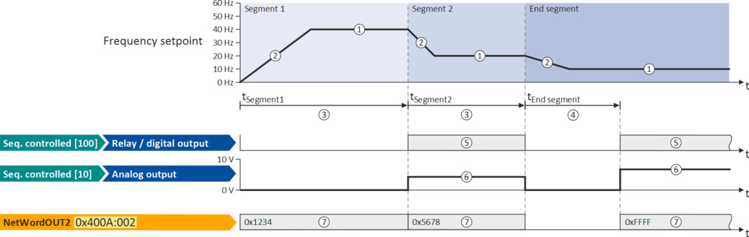
The following figure shows the segment settings relevant for the operating mode 0x6060 (P301.00) = "MS: Velocity mode [-2]".
–
The table below provides a brief overview of the possible settings of the different segments.
|
Setting
|
Info
|
|
|
Frequency setpoint
|
①
|
Only relevant for the operating mode 0x6060 (P301.00) = "MS: Velocity mode [-2]”. The direction of rotation is implemented according to the sign.
|
|
Acceleration/deceleration
|
②
|
Only relevant for the operating mode 0x6060 (P301.00) = "MS: Velocity mode [-2]”. The set time refers to the acceleration from standstill to the set maximum frequency. The deceleration is effected with the same ramp.
|
|
Time
|
③
|
Meaning for segment 1 ... 8:
Runtime for the segment after the expiration of which it is switched over to the next step of the sequence. Only relevant for Sequencer mode 0x4025 (P800.00) = "Time operation [1]" or "Time & step operation [3]".
|
|
④
|
Meaning for end segment:
Delay time for activating the output states configured for the end segment.
|
|
|
Digital outputs
|
⑤
|
Optionally: Set digital outputs to a certain level for the execution time of the segment.
|
|
Analog outputs
|
⑥
|
Optionally: Set analog outputs to an adjustable voltage value for the execution time of the segment.
|
|
PID setpoint
|
|
Only relevant if the PID control in 0x4020:001 (P600.01) is activated.
|
|
Torque setpoint
|
|
Only relevant for the operating mode 0x6060 (P301.00) = "MS: Torque mode [-1]”.
|
|
NetWordOUT2
|
⑦
|
Optionally: Set the NetWordOUT2 data word to an adjustable value for the execution time of the segment. The NetWordOUT2 data word 0x400A:002 (P591.02) can be mapped to a network register to transfer the set value as process date.
|
 Configuring the process controller
In the following, all parameters relevant for the segment configuration are given.

If the sequencer is active, write accesses to all parameters are blocked that concern the active segment configuration!
Parameter
|
Address
|
Name / setting range / [default setting]
|
Information
|
|
|
0x4026:001
(P801.01)
|
Sequencer segment 1: Frequency setpoint
(Segment 1: Frequency setp.)
-599.0 ... [0.0] ... 599.0 Hz
–
From version 03.00
|
Frequency setpoint for the segment.
–
Only relevant for operating mode 0x6060 (P301.00) = "MS: Velocity mode [-2]".
–
Direction of rotation according to sign.
|
|
|
0x4026:002
(P801.02)
|
Sequencer segment 1: Acceleration/deceleration
(Segment 1: Accel./decel.)
0.0 ... [5.0] ... 3600.0 s
–
From version 03.00
|
Acceleration/deceleration for the segment.
–
Only relevant for operating mode 0x6060 (P301.00) = "MS: Velocity mode [-2]".
–
The set time refers to the acceleration from standstill to the set maximum frequency. The deceleration is effected with the same ramp.
|
|
|
0x4026:003
(P801.03)
|
Sequencer segment 1: Time
(Segment 1: Time)
0.0 ... [0.0] ... 100000.0 s
–
From version 03.00
|
Runtime for the segment after the expiry of which it is switched over to the next step of the sequence.
–
Only relevant for Sequencer mode 0x4025 (P800.00) = "Time operation [1]" or "Time & step operation [3]".
–
With the setting "0.0", the segment will be skipped.
|
|
|
0x4026:004
(P801.04)
|
Sequencer segment 1: Digital outputs
(Segment 1: Digital outp.)
0 ... [0] ... 255
–
From version 03.00
|
Optionally: Set digital outputs to the level set here for the execution time of the segment.
Note!
In order that the control of a digital output is executed by the sequencer, the following assignment must be made for the respective digital output: –
Relay: 0x2634:001 (P420.01) = "Sequencer controlled [100]"
–
Digital output 1: 0x2634:002 (P420.02) = "Sequencer controlled [100]"
–
Digital output 2: 0x2634:003 (P420.03) = "Sequencer controlled [100]"
|
|
|
Bit
0
|
Relay
|
0 = X9/NO-COM open and NC-COM closed.
1 = X9/NO-COM closed and NC-COM open.
An inversion set in 0x2635:001 (P421.01)is taken into consideration here.
|
|
|
Bit
1
|
Digital output 1
|
0 = set digital output 1 to LOW level.
1 = set digital output 1 to HIGH level.
An inversion set in 0x2635:002 (P421.02) is taken into consideration here.
|
|
|
Bit
2
|
Digital output 2
|
0 = set digital output 2 to LOW level.
1 = set digital output 2 to HIGH level.
An inversion set in 0x2635:003 (P421.03) is taken into consideration here.
|
|
|
0x4026:005
(P801.05)
|
Sequencer segment 1: Analog outputs
(Segment 1: Analog outp.)
0.00 ... [0.00] ... 10.00 VDC
–
From version 03.00
|
Optionally: Set analog outputs to the voltage value set here for the execution time of the segment.
Note!
In order that the control of an analog output is executed by the sequencer, the following assignment must be made for the respective analog output: –
Analog output 1: 0x2639:002 (P440.02) = "Sequencer controlled [10]"
–
Analog output 2: 0x263A:002 (P441.02) = "Sequencer controlled [10]"
|
|
|
0x4026:006
(P801.06)
|
Sequencer segment 1: PID setpoint
(Segment 1: PID setp.)
-300.00 ... [0.00] ... 300.00 PID unit
–
From version 03.00
|
PID control value for the segment.
|
|
|
0x4026:007
(P801.07)
|
Sequencer segment 1: Torque setpoint
(Segment 1: Torque setp.)
-400.0 ... [100.0] ... 400.0 %
–
From version 03.00
|
Torque setpoint for the segment.
|
|
|
0x4026:008
|
Sequencer segment 1: NetWordOUT2
0 ... [0] ... 65535
–
From version 03.00
|
Optionally: Set the NetWordOUT2 data word to the value set here for the execution time of the segment.
–
The NetWordOUT2 data word 0x400A:002 (P591.02) can be mapped to a network register to transfer the set value as process date.
|
|
|
0x4026:009
|
Sequencer segment 1: Reserved
0 ... [0] ... 4294967295.0
–
From version 03.00
|
||
|
0x4027:001
(P802.01)
|
Sequencer segment 2: Frequency setpoint
(Segment 2: Frequency setp.)
-599.0 ... [0.0] ... 599.0 Hz
–
From version 03.00
|
Frequency setpoint for the segment.
–
Only relevant for operating mode 0x6060 (P301.00) = "MS: Velocity mode [-2]".
–
Direction of rotation according to sign.
|
|
|
0x4027:002
(P802.02)
|
Sequencer segment 2: Acceleration/deceleration
(Segment 2: Accel./decel.)
0.0 ... [5.0] ... 3600.0 s
–
From version 03.00
|
Acceleration/deceleration for the segment.
–
Only relevant for operating mode 0x6060 (P301.00) = "MS: Velocity mode [-2]".
–
The set time refers to the acceleration from standstill to the set maximum frequency. The deceleration is effected with the same ramp.
|
|
|
0x4027:003
(P802.03)
|
Sequencer segment 2: Time
(Segment 2: Time)
0.0 ... [0.0] ... 100000.0 s
–
From version 03.00
|
Runtime for the segment after the expiry of which it is switched over to the next step of the sequence.
–
Only relevant for Sequencer mode 0x4025 (P800.00) = "Time operation [1]" or "Time & step operation [3]".
–
With the setting "0.0", the segment will be skipped.
|
|
|
0x4027:004
(P802.04)
|
Sequencer segment 2: Digital outputs
(Segment 2: Digital outp.)
0 ... [0] ... 255
–
From version 03.00
|
Optionally: Set digital outputs to the level set here for the execution time of the segment.
Note!
In order that the control of a digital output is executed by the sequencer, the following assignment must be made for the respective digital output: –
Relay: 0x2634:001 (P420.01) = "Sequencer controlled [100]"
–
Digital output 1: 0x2634:002 (P420.02) = "Sequencer controlled [100]"
–
Digital output 2: 0x2634:003 (P420.03) = "Sequencer controlled [100]"
|
|
|
Bit
0
|
Relay
|
0 = X9/NO-COM open and NC-COM closed.
1 = X9/NO-COM closed and NC-COM open.
An inversion set in 0x2635:001 (P421.01)is taken into consideration here.
|
|
|
Bit
1
|
Digital output 1
|
0 = set digital output 1 to LOW level.
1 = set digital output 1 to HIGH level.
An inversion set in 0x2635:002 (P421.02) is taken into consideration here.
|
|
|
Bit
2
|
Digital output 2
|
0 = set digital output 2 to LOW level.
1 = set digital output 2 to HIGH level.
An inversion set in 0x2635:003 (P421.03) is taken into consideration here.
|
|
|
0x4027:005
(P802.05)
|
Sequencer segment 2: Analog outputs
(Segment 2: Analog outp.)
0.00 ... [0.00] ... 10.00 VDC
–
From version 03.00
|
Optionally: Set analog outputs to the voltage value set here for the execution time of the segment.
Note!
In order that the control of an analog output is executed by the sequencer, the following assignment must be made for the respective analog output: –
Analog output 1: 0x2639:002 (P440.02) = "Sequencer controlled [10]"
–
Analog output 2: 0x263A:002 (P441.02) = "Sequencer controlled [10]"
|
|
|
0x4027:006
(P802.06)
|
Sequencer segment 2: PID setpoint
(Segment 2: PID setp.)
-300.00 ... [0.00] ... 300.00 PID unit
–
From version 03.00
|
PID control value for the segment.
|
|
|
0x4027:007
(P802.07)
|
Sequencer segment 2: Torque setpoint
(Segment 2: Torque setp.)
-400.0 ... [100.0] ... 400.0 %
–
From version 03.00
|
Torque setpoint for the segment.
|
|
|
0x4027:008
|
Sequencer segment 2: NetWordOUT2
0 ... [0] ... 65535
–
From version 03.00
|
Optionally: Set the NetWordOUT2 data word to the value set here for the execution time of the segment.
–
The NetWordOUT2 data word 0x400A:002 (P591.02) can be mapped to a network register to transfer the set value as process date.
|
|
|
0x4027:009
|
Sequencer segment 2: Reserved
0 ... [0] ... 4294967295.0
–
From version 03.00
|
||
|
0x4028:001
(P803.01)
|
Sequencer segment 3: Frequency setpoint
(Segment 3: Frequency setp.)
-599.0 ... [0.0] ... 599.0 Hz
–
From version 03.00
|
Frequency setpoint for the segment.
–
Only relevant for operating mode 0x6060 (P301.00) = "MS: Velocity mode [-2]".
–
Direction of rotation according to sign.
|
|
|
0x4028:002
(P803.02)
|
Sequencer segment 3: Acceleration/deceleration
(Segment 3: Accel./decel.)
0.0 ... [5.0] ... 3600.0 s
–
From version 03.00
|
Acceleration/deceleration for the segment.
–
Only relevant for operating mode 0x6060 (P301.00) = "MS: Velocity mode [-2]".
–
The set time refers to the acceleration from standstill to the set maximum frequency. The deceleration is effected with the same ramp.
|
|
|
0x4028:003
(P803.03)
|
Sequencer segment 3: Time
(Segment 3: Time)
0.0 ... [0.0] ... 100000.0 s
–
From version 03.00
|
Runtime for the segment after the expiry of which it is switched over to the next step of the sequence.
–
Only relevant for Sequencer mode 0x4025 (P800.00) = "Time operation [1]" or "Time & step operation [3]".
–
With the setting "0.0", the segment will be skipped.
|
|
|
0x4028:004
(P803.04)
|
Sequencer segment 3: Digital outputs
(Segment 3: Digital outp.)
0 ... [0] ... 255
–
From version 03.00
|
Optionally: Set digital outputs to the level set here for the execution time of the segment.
Note!
In order that the control of a digital output is executed by the sequencer, the following assignment must be made for the respective digital output: –
Relay: 0x2634:001 (P420.01) = "Sequencer controlled [100]"
–
Digital output 1: 0x2634:002 (P420.02) = "Sequencer controlled [100]"
–
Digital output 2: 0x2634:003 (P420.03) = "Sequencer controlled [100]"
|
|
|
Bit
0
|
Relay
|
0 = X9/NO-COM open and NC-COM closed.
1 = X9/NO-COM closed and NC-COM open.
An inversion set in 0x2635:001 (P421.01)is taken into consideration here.
|
|
|
Bit
1
|
Digital output 1
|
0 = set digital output 1 to LOW level.
1 = set digital output 1 to HIGH level.
An inversion set in 0x2635:002 (P421.02) is taken into consideration here.
|
|
|
Bit
2
|
Digital output 2
|
0 = set digital output 2 to LOW level.
1 = set digital output 2 to HIGH level.
An inversion set in 0x2635:003 (P421.03) is taken into consideration here.
|
|
|
0x4028:005
(P803.05)
|
Sequencer segment 3: Analog outputs
(Segment 3: Analog outp.)
0.00 ... [0.00] ... 10.00 VDC
–
From version 03.00
|
Optionally: Set analog outputs to the voltage value set here for the execution time of the segment.
Note!
In order that the control of an analog output is executed by the sequencer, the following assignment must be made for the respective analog output: –
Analog output 1: 0x2639:002 (P440.02) = "Sequencer controlled [10]"
–
Analog output 2: 0x263A:002 (P441.02) = "Sequencer controlled [10]"
|
|
|
0x4028:006
(P803.06)
|
Sequencer segment 3: PID setpoint
(Segment 3: PID setp.)
-300.00 ... [0.00] ... 300.00 PID unit
–
From version 03.00
|
PID control value for the segment.
|
|
|
0x4028:007
(P803.07)
|
Sequencer segment 3: Torque setpoint
(Segment 3: Torque setp.)
-400.0 ... [100.0] ... 400.0 %
–
From version 03.00
|
Torque setpoint for the segment.
|
|
|
0x4028:008
|
Sequencer segment 3: NetWordOUT2
0 ... [0] ... 65535
–
From version 03.00
|
Optionally: Set the NetWordOUT2 data word to the value set here for the execution time of the segment.
–
The NetWordOUT2 data word 0x400A:002 (P591.02) can be mapped to a network register to transfer the set value as process date.
|
|
|
0x4028:009
|
Sequencer segment 3: Reserved
0 ... [0] ... 4294967295.0
–
From version 03.00
|
||
|
0x4029:001
(P804.01)
|
Sequencer segment 4: Frequency setpoint
(Segment 4: Frequency setp.)
-599.0 ... [0.0] ... 599.0 Hz
–
From version 03.00
|
Frequency setpoint for the segment.
–
Only relevant for operating mode 0x6060 (P301.00) = "MS: Velocity mode [-2]".
–
Direction of rotation according to sign.
|
|
|
0x4029:002
(P804.02)
|
Sequencer segment 4: Acceleration/deceleration
(Segment 4: Accel./decel.)
0.0 ... [5.0] ... 3600.0 s
–
From version 03.00
|
Acceleration/deceleration for the segment.
–
Only relevant for operating mode 0x6060 (P301.00) = "MS: Velocity mode [-2]".
–
The set time refers to the acceleration from standstill to the set maximum frequency. The deceleration is effected with the same ramp.
|
|
|
0x4029:003
(P804.03)
|
Sequencer segment 4: Time
(Segment 4: Time)
0.0 ... [0.0] ... 100000.0 s
–
From version 03.00
|
Runtime for the segment after the expiry of which it is switched over to the next step of the sequence.
–
Only relevant for Sequencer mode 0x4025 (P800.00) = "Time operation [1]" or "Time & step operation [3]".
–
With the setting "0.0", the segment will be skipped.
|
|
|
0x4029:004
(P804.04)
|
Sequencer segment 4: Digital outputs
(Segment 4: Digital outp.)
0 ... [0] ... 255
–
From version 03.00
|
Optionally: Set digital outputs to the level set here for the execution time of the segment.
Note!
In order that the control of a digital output is executed by the sequencer, the following assignment must be made for the respective digital output: –
Relay: 0x2634:001 (P420.01) = "Sequencer controlled [100]"
–
Digital output 1: 0x2634:002 (P420.02) = "Sequencer controlled [100]"
–
Digital output 2: 0x2634:003 (P420.03) = "Sequencer controlled [100]"
|
|
|
Bit
0
|
Relay
|
0 = X9/NO-COM open and NC-COM closed.
1 = X9/NO-COM closed and NC-COM open.
An inversion set in 0x2635:001 (P421.01)is taken into consideration here.
|
|
|
Bit
1
|
Digital output 1
|
0 = set digital output 1 to LOW level.
1 = set digital output 1 to HIGH level.
An inversion set in 0x2635:002 (P421.02) is taken into consideration here.
|
|
|
Bit
2
|
Digital output 2
|
0 = set digital output 2 to LOW level.
1 = set digital output 2 to HIGH level.
An inversion set in 0x2635:003 (P421.03) is taken into consideration here.
|
|
|
0x4029:005
(P804.05)
|
Sequencer segment 4: Analog outputs
(Segment 4: Analog outp.)
0.00 ... [0.00] ... 10.00 VDC
–
From version 03.00
|
Optionally: Set analog outputs to the voltage value set here for the execution time of the segment.
Note!
In order that the control of an analog output is executed by the sequencer, the following assignment must be made for the respective analog output: –
Analog output 1: 0x2639:002 (P440.02) = "Sequencer controlled [10]"
–
Analog output 2: 0x263A:002 (P441.02) = "Sequencer controlled [10]"
|
|
|
0x4029:006
(P804.06)
|
Sequencer segment 4: PID setpoint
(Segment 4: PID setp.)
-300.00 ... [0.00] ... 300.00 PID unit
–
From version 03.00
|
PID control value for the segment.
|
|
|
0x4029:007
(P804.07)
|
Sequencer segment 4: Torque setpoint
(Segment 4: Torque setp.)
-400.0 ... [100.0] ... 400.0 %
–
From version 03.00
|
Torque setpoint for the segment.
|
|
|
0x4029:008
|
Sequencer segment 4: NetWordOUT2
0 ... [0] ... 65535
–
From version 03.00
|
Optionally: Set the NetWordOUT2 data word to the value set here for the execution time of the segment.
–
The NetWordOUT2 data word 0x400A:002 (P591.02) can be mapped to a network register to transfer the set value as process date.
|
|
|
0x4029:009
|
Sequencer segment 4: Reserved
0 ... [0] ... 4294967295.0
–
From version 03.00
|
||
|
0x402A:001
(P805.01)
|
Sequencer segment 5: Frequency setpoint
(Segment 5: Frequency setp.)
-599.0 ... [0.0] ... 599.0 Hz
–
From version 03.00
|
Frequency setpoint for the segment.
–
Only relevant for operating mode 0x6060 (P301.00) = "MS: Velocity mode [-2]".
–
Direction of rotation according to sign.
|
|
|
0x402A:002
(P805.02)
|
Sequencer segment 5: Acceleration/deceleration
(Segment 5: Accel./decel.)
0.0 ... [5.0] ... 3600.0 s
–
From version 03.00
|
Acceleration/deceleration for the segment.
–
Only relevant for operating mode 0x6060 (P301.00) = "MS: Velocity mode [-2]".
–
The set time refers to the acceleration from standstill to the set maximum frequency. The deceleration is effected with the same ramp.
|
|
|
0x402A:003
(P805.03)
|
Sequencer segment 5: Time
(Segment 5: Time)
0.0 ... [0.0] ... 100000.0 s
–
From version 03.00
|
Runtime for the segment after the expiry of which it is switched over to the next step of the sequence.
–
Only relevant for Sequencer mode 0x4025 (P800.00) = "Time operation [1]" or "Time & step operation [3]".
–
With the setting "0.0", the segment will be skipped.
|
|
|
0x402A:004
(P805.04)
|
Sequencer segment 5: Digital outputs
(Segment 5: Digital outp.)
0 ... [0] ... 255
–
From version 03.00
|
Optionally: Set digital outputs to the level set here for the execution time of the segment.
Note!
In order that the control of a digital output is executed by the sequencer, the following assignment must be made for the respective digital output: –
Relay: 0x2634:001 (P420.01) = "Sequencer controlled [100]"
–
Digital output 1: 0x2634:002 (P420.02) = "Sequencer controlled [100]"
–
Digital output 2: 0x2634:003 (P420.03) = "Sequencer controlled [100]"
|
|
|
Bit
0
|
Relay
|
0 = X9/NO-COM open and NC-COM closed.
1 = X9/NO-COM closed and NC-COM open.
An inversion set in 0x2635:001 (P421.01)is taken into consideration here.
|
|
|
Bit
1
|
Digital output 1
|
0 = set digital output 1 to LOW level.
1 = set digital output 1 to HIGH level.
An inversion set in 0x2635:002 (P421.02) is taken into consideration here.
|
|
|
Bit
2
|
Digital output 2
|
0 = set digital output 2 to LOW level.
1 = set digital output 2 to HIGH level.
An inversion set in 0x2635:003 (P421.03) is taken into consideration here.
|
|
|
0x402A:005
(P805.05)
|
Sequencer segment 5: Analog outputs
(Segment 5: Analog outp.)
0.00 ... [0.00] ... 10.00 VDC
–
From version 03.00
|
Optionally: Set analog outputs to the voltage value set here for the execution time of the segment.
Note!
In order that the control of an analog output is executed by the sequencer, the following assignment must be made for the respective analog output: –
Analog output 1: 0x2639:002 (P440.02) = "Sequencer controlled [10]"
–
Analog output 2: 0x263A:002 (P441.02) = "Sequencer controlled [10]"
|
|
|
0x402A:006
(P805.06)
|
Sequencer segment 5: PID setpoint
(Segment 5: PID setp.)
-300.00 ... [0.00] ... 300.00 PID unit
–
From version 03.00
|
PID control value for the segment.
|
|
|
0x402A:007
(P805.07)
|
Sequencer segment 5: Torque setpoint
(Segment 5: Torque setp.)
-400.0 ... [100.0] ... 400.0 %
–
From version 03.00
|
Torque setpoint for the segment.
|
|
|
0x402A:008
|
Sequencer segment 5: NetWordOUT2
0 ... [0] ... 65535
–
From version 03.00
|
Optionally: Set the NetWordOUT2 data word to the value set here for the execution time of the segment.
–
The NetWordOUT2 data word 0x400A:002 (P591.02) can be mapped to a network register to transfer the set value as process date.
|
|
|
0x402A:009
|
Sequencer segment 5: Reserved
0 ... [0] ... 4294967295.0
–
From version 03.00
|
||
|
0x402B:001
(P806.01)
|
Sequencer segment 6: Frequency setpoint
(Segment 6: Frequency setp.)
-599.0 ... [0.0] ... 599.0 Hz
–
From version 03.00
|
Frequency setpoint for the segment.
–
Only relevant for operating mode 0x6060 (P301.00) = "MS: Velocity mode [-2]".
–
Direction of rotation according to sign.
|
|
|
0x402B:002
(P806.02)
|
Sequencer segment 6: Acceleration/deceleration
(Segment 6: Accel./decel.)
0.0 ... [5.0] ... 3600.0 s
–
From version 03.00
|
Acceleration/deceleration for the segment.
–
Only relevant for operating mode 0x6060 (P301.00) = "MS: Velocity mode [-2]".
–
The set time refers to the acceleration from standstill to the set maximum frequency. The deceleration is effected with the same ramp.
|
|
|
0x402B:003
(P806.03)
|
Sequencer segment 6: Time
(Segment 6: Time)
0.0 ... [0.0] ... 100000.0 s
–
From version 03.00
|
Runtime for the segment after the expiry of which it is switched over to the next step of the sequence.
–
Only relevant for Sequencer mode 0x4025 (P800.00) = "Time operation [1]" or "Time & step operation [3]".
–
With the setting "0.0", the segment will be skipped.
|
|
|
0x402B:004
(P806.04)
|
Sequencer segment 6: Digital outputs
(Segment 6: Digital outp.)
0 ... [0] ... 255
–
From version 03.00
|
Optionally: Set digital outputs to the level set here for the execution time of the segment.
Note!
In order that the control of a digital output is executed by the sequencer, the following assignment must be made for the respective digital output: –
Relay: 0x2634:001 (P420.01) = "Sequencer controlled [100]"
–
Digital output 1: 0x2634:002 (P420.02) = "Sequencer controlled [100]"
–
Digital output 2: 0x2634:003 (P420.03) = "Sequencer controlled [100]"
|
|
|
Bit
0
|
Relay
|
0 = X9/NO-COM open and NC-COM closed.
1 = X9/NO-COM closed and NC-COM open.
An inversion set in 0x2635:001 (P421.01)is taken into consideration here.
|
|
|
Bit
1
|
Digital output 1
|
0 = set digital output 1 to LOW level.
1 = set digital output 1 to HIGH level.
An inversion set in 0x2635:002 (P421.02) is taken into consideration here.
|
|
|
Bit
2
|
Digital output 2
|
0 = set digital output 2 to LOW level.
1 = set digital output 2 to HIGH level.
An inversion set in 0x2635:003 (P421.03) is taken into consideration here.
|
|
|
0x402B:005
(P806.05)
|
Sequencer segment 6: Analog outputs
(Segment 6: Analog outp.)
0.00 ... [0.00] ... 10.00 VDC
–
From version 03.00
|
Optionally: Set analog outputs to the voltage value set here for the execution time of the segment.
Note!
In order that the control of an analog output is executed by the sequencer, the following assignment must be made for the respective analog output: –
Analog output 1: 0x2639:002 (P440.02) = "Sequencer controlled [10]"
–
Analog output 2: 0x263A:002 (P441.02) = "Sequencer controlled [10]"
|
|
|
0x402B:006
(P806.06)
|
Sequencer segment 6: PID setpoint
(Segment 6: PID setp.)
-300.00 ... [0.00] ... 300.00 PID unit
–
From version 03.00
|
PID control value for the segment.
|
|
|
0x402B:007
(P806.07)
|
Sequencer segment 6: Torque setpoint
(Segment 6: Torque setp.)
-400.0 ... [100.0] ... 400.0 %
–
From version 03.00
|
Torque setpoint for the segment.
|
|
|
0x402B:008
|
Sequencer segment 6: NetWordOUT2
0 ... [0] ... 65535
–
From version 03.00
|
Optionally: Set the NetWordOUT2 data word to the value set here for the execution time of the segment.
–
The NetWordOUT2 data word 0x400A:002 (P591.02) can be mapped to a network register to transfer the set value as process date.
|
|
|
0x402B:009
|
Sequencer segment 6: Reserved
0 ... [0] ... 4294967295.0
–
From version 03.00
|
||
|
0x402C:001
(P807.01)
|
Sequencer segment 7: Frequency setpoint
(Segment 7: Frequency setp.)
-599.0 ... [0.0] ... 599.0 Hz
–
From version 03.00
|
Frequency setpoint for the segment.
–
Only relevant for operating mode 0x6060 (P301.00) = "MS: Velocity mode [-2]".
–
Direction of rotation according to sign.
|
|
|
0x402C:002
(P807.02)
|
Sequencer segment 7: Acceleration/deceleration
(Segment 7: Accel./decel.)
0.0 ... [5.0] ... 3600.0 s
–
From version 03.00
|
Acceleration/deceleration for the segment.
–
Only relevant for operating mode 0x6060 (P301.00) = "MS: Velocity mode [-2]".
–
The set time refers to the acceleration from standstill to the set maximum frequency. The deceleration is effected with the same ramp.
|
|
|
0x402C:003
(P807.03)
|
Sequencer segment 7: Time
(Segment 7: Time)
0.0 ... [0.0] ... 100000.0 s
–
From version 03.00
|
Runtime for the segment after the expiry of which it is switched over to the next step of the sequence.
–
Only relevant for Sequencer mode 0x4025 (P800.00) = "Time operation [1]" or "Time & step operation [3]".
–
With the setting "0.0", the segment will be skipped.
|
|
|
0x402C:004
(P807.04)
|
Sequencer segment 7: Digital outputs
(Segment 7: Digital outp.)
0 ... [0] ... 255
–
From version 03.00
|
Optionally: Set digital outputs to the level set here for the execution time of the segment.
Note!
In order that the control of a digital output is executed by the sequencer, the following assignment must be made for the respective digital output: –
Relay: 0x2634:001 (P420.01) = "Sequencer controlled [100]"
–
Digital output 1: 0x2634:002 (P420.02) = "Sequencer controlled [100]"
–
Digital output 2: 0x2634:003 (P420.03) = "Sequencer controlled [100]"
|
|
|
Bit
0
|
Relay
|
0 = X9/NO-COM open and NC-COM closed.
1 = X9/NO-COM closed and NC-COM open.
An inversion set in 0x2635:001 (P421.01)is taken into consideration here.
|
|
|
Bit
1
|
Digital output 1
|
0 = set digital output 1 to LOW level.
1 = set digital output 1 to HIGH level.
An inversion set in 0x2635:002 (P421.02) is taken into consideration here.
|
|
|
Bit
2
|
Digital output 2
|
0 = set digital output 2 to LOW level.
1 = set digital output 2 to HIGH level.
An inversion set in 0x2635:003 (P421.03) is taken into consideration here.
|
|
|
0x402C:005
(P807.05)
|
Sequencer segment 7: Analog outputs
(Segment 7: Analog outp.)
0.00 ... [0.00] ... 10.00 VDC
–
From version 03.00
|
Optionally: Set analog outputs to the voltage value set here for the execution time of the segment.
Note!
In order that the control of an analog output is executed by the sequencer, the following assignment must be made for the respective analog output: –
Analog output 1: 0x2639:002 (P440.02) = "Sequencer controlled [10]"
–
Analog output 2: 0x263A:002 (P441.02) = "Sequencer controlled [10]"
|
|
|
0x402C:006
(P807.06)
|
Sequencer segment 7: PID setpoint
(Segment 7: PID setp.)
-300.00 ... [0.00] ... 300.00 PID unit
–
From version 03.00
|
PID control value for the segment.
|
|
|
0x402C:007
(P807.07)
|
Sequencer segment 7: Torque setpoint
(Segment 7: Torque setp.)
-400.0 ... [100.0] ... 400.0 %
–
From version 03.00
|
Torque setpoint for the segment.
|
|
|
0x402C:008
|
Sequencer segment 7: NetWordOUT2
0 ... [0] ... 65535
–
From version 03.00
|
Optionally: Set the NetWordOUT2 data word to the value set here for the execution time of the segment.
–
The NetWordOUT2 data word 0x400A:002 (P591.02) can be mapped to a network register to transfer the set value as process date.
|
|
|
0x402C:009
|
Sequencer segment 7: Reserved
0 ... [0] ... 4294967295.0
–
From version 03.00
|
||
|
0x402D:001
(P808.01)
|
Sequencer segment 8: Frequency setpoint
(Segment 8: Frequency setp.)
-599.0 ... [0.0] ... 599.0 Hz
–
From version 03.00
|
Frequency setpoint for the segment.
–
Only relevant for operating mode 0x6060 (P301.00) = "MS: Velocity mode [-2]".
–
Direction of rotation according to sign.
|
|
|
0x402D:002
(P808.02)
|
Sequencer segment 8: Acceleration/deceleration
(Segment 8: Accel./decel.)
0.0 ... [5.0] ... 3600.0 s
–
From version 03.00
|
Acceleration/deceleration for the segment.
–
Only relevant for operating mode 0x6060 (P301.00) = "MS: Velocity mode [-2]".
–
The set time refers to the acceleration from standstill to the set maximum frequency. The deceleration is effected with the same ramp.
|
|
|
0x402D:003
(P808.03)
|
Sequencer segment 8: Time
(Segment 8: Time)
0.0 ... [0.0] ... 100000.0 s
–
From version 03.00
|
Runtime for the segment after the expiry of which it is switched over to the next step of the sequence.
–
Only relevant for Sequencer mode 0x4025 (P800.00) = "Time operation [1]" or "Time & step operation [3]".
–
With the setting "0.0", the segment will be skipped.
|
|
|
0x402D:004
(P808.04)
|
Sequencer segment 8: Digital outputs
(Segment 8: Digital outp.)
0 ... [0] ... 255
–
From version 03.00
|
Optionally: Set digital outputs to the level set here for the execution time of the segment.
Note!
In order that the control of a digital output is executed by the sequencer, the following assignment must be made for the respective digital output: –
Relay: 0x2634:001 (P420.01) = "Sequencer controlled [100]"
–
Digital output 1: 0x2634:002 (P420.02) = "Sequencer controlled [100]"
–
Digital output 2: 0x2634:003 (P420.03) = "Sequencer controlled [100]"
|
|
|
Bit
0
|
Relay
|
0 = X9/NO-COM open and NC-COM closed.
1 = X9/NO-COM closed and NC-COM open.
An inversion set in 0x2635:001 (P421.01)is taken into consideration here.
|
|
|
Bit
1
|
Digital output 1
|
0 = set digital output 1 to LOW level.
1 = set digital output 1 to HIGH level.
An inversion set in 0x2635:002 (P421.02) is taken into consideration here.
|
|
|
Bit
2
|
Digital output 2
|
0 = set digital output 2 to LOW level.
1 = set digital output 2 to HIGH level.
An inversion set in 0x2635:003 (P421.03) is taken into consideration here.
|
|
|
0x402D:005
(P808.05)
|
Sequencer segment 8: Analog outputs
(Segment 8: Analog outp.)
0.00 ... [0.00] ... 10.00 VDC
–
From version 03.00
|
Optionally: Set analog outputs to the voltage value set here for the execution time of the segment.
Note!
In order that the control of an analog output is executed by the sequencer, the following assignment must be made for the respective analog output: –
Analog output 1: 0x2639:002 (P440.02) = "Sequencer controlled [10]"
–
Analog output 2: 0x263A:002 (P441.02) = "Sequencer controlled [10]"
|
|
|
0x402D:006
(P808.06)
|
Sequencer segment 8: PID setpoint
(Segment 8: PID setp.)
-300.00 ... [0.00] ... 300.00 PID unit
–
From version 03.00
|
PID control value for the segment.
|
|
|
0x402D:007
(P808.07)
|
Sequencer segment 8: Torque setpoint
(Segment 8: Torque setp.)
-400.0 ... [100.0] ... 400.0 %
–
From version 03.00
|
Torque setpoint for the segment.
|
|
|
0x402D:008
|
Sequencer segment 8: NetWordOUT2
0 ... [0] ... 65535
–
From version 03.00
|
Optionally: Set the NetWordOUT2 data word to the value set here for the execution time of the segment.
–
The NetWordOUT2 data word 0x400A:002 (P591.02) can be mapped to a network register to transfer the set value as process date.
|
|
|
0x402D:009
|
Sequencer segment 8: Reserved
0 ... [0] ... 4294967295.0
–
From version 03.00
|
||
|
0x402E:001
(P822.01)
|
End segment: Frequency setpoint
(End segment: Frequency setp.)
-599.0 ... [0.0] ... 599.0 Hz
–
From version 03.00
|
Frequency setpoint after the sequence has been completed, i. e., after the steps configured for the sequence have been passed through with the set numbers of cycles.
–
Only relevant for the operating mode 0x6060 (P301.00) = "MS: Velocity mode [-2]" and if end of sequence mode 0x402F (P824.00) = "Keep running [0]".
–
Direction of rotation according to sign.
|
|
|
0x402E:002
(P822.02)
|
End segment: Acceleration/deceleration
(End segment: Accel./decel.)
0.0 ... [5.0] ... 3600.0 s
–
From version 03.00
|
If end of sequence mode = "continuous operation" (default setting): Acceleration/deceleration for reaching the frequency setpoint set for the end segment after the sequence has been processed.
If end of sequence mode = "Stop" or "Stop and abort": Deceleration for reaching standstill after the sequence has been processed.
–
Only relevant for operating mode 0x6060 (P301.00) = "MS: Velocity mode [-2]".
–
The set time refers to the acceleration from standstill to the set maximum frequency. The deceleration is effected with the same ramp.
|
|
|
0x402E:003
(P822.03)
|
End segment: Time
(End segment: Time)
0.0 ... [0.0] ... 100000.0 s
–
From version 03.00
|
Delay time for activating the output states configured for the end segment.
–
This parameter has a different meaning than the time settings for the segments 1 ... 8!
–
The set deceleration time starts when the end segment is started to be processed.
After the deceleration time has elapsed:
–
The digital outputs are (if configured accordingly) set to the levels set in 0x402E:004 (P822.04).
–
The analog outputs are (if configured accordingly) set to the voltage value set in 0x402E:005 (P822.05).
–
The NetWordOUT2 data word is set to the value set in 0x402E:008.
|
|
|
0x402E:004
(P822.04)
|
End segment: Digital outputs
(End segment: Digital outp.)
0 ... [0] ... 255
–
From version 03.00
|
Optionally: Set digital outputs to the levels set here after the time set for the end segment.
|
|
|
Bit
0
|
Relay
|
0 = X9/NO-COM open and NC-COM closed.
1 = X9/NO-COM closed and NC-COM open.
An inversion set in 0x2635:001 (P421.01)is taken into consideration here.
|
|
|
Bit
1
|
Digital output 1
|
0 = set digital output 1 to LOW level.
1 = set digital output 1 to HIGH level.
An inversion set in 0x2635:002 (P421.02) is taken into consideration here.
|
|
|
Bit
2
|
Digital output 2
|
0 = set digital output 2 to LOW level.
1 = set digital output 2 to HIGH level.
An inversion set in 0x2635:003 (P421.03) is taken into consideration here.
|
|
|
0x402E:005
(P822.05)
|
End segment: Analog outputs
(End segment: Analog outp.)
0.00 ... [0.00] ... 10.00 VDC
–
From version 03.00
|
Optionally: Set analog outputs to the voltage value set here after the time set for the end segment.
Note!
In order that the control of an analog output is executed by the sequencer, the following assignment must be made for the respective analog output: –
Analog output 1: 0x2639:002 (P440.02) = "Sequencer controlled [10]"
–
Analog output 2: 0x263A:002 (P441.02) = "Sequencer controlled [10]"
|
|
|
0x402E:006
(P822.06)
|
End segment: PID setpoint
(End segment: PID setp.)
-300.00 ... [0.00] ... 300.00 PID unit
–
From version 03.00
|
PID control value after the sequence has been completed, i. e., after the steps configured for the sequence have been passed through with the set numbers of cycles.
–
Only relevant if PID control is activated in 0x4020:001 (P600.01) and end of sequence mode 0x402F (P824.00) = "Keep running [0]".
|
|
|
0x402E:007
(P822.07)
|
End segment: Torque setpoint
(End segment: Torque setp.)
-400.0 ... [100.0] ... 400.0 %
–
From version 03.00
|
Torque setpoint after the sequence has been completed, i. e., after the steps configured for the sequence have been passed through with the set numbers of cycles.
–
Only relevant for the operating mode 0x6060 (P301.00) = "MS: Torque mode [-1]" and if end of sequence mode 0x402F (P824.00) = "Keep running [0]".
|
|
|
0x402E:008
|
End segment: NetWordOUT2
0 ... [0] ... 65535
–
From version 03.00
|
Optionally: Set NetWordOUT2 data word to the value set here after the time set for the end segment.
–
The NetWordOUT2 data word 0x400A:002 (P591.02) can be mapped to a network register to transfer the set value as process date.
|
|
|
0x402E:009
|
End segment: Reserved
0 ... [0] ... 4294967295.0
–
From version 03.00
|
||